Protector® Controlled Atmosphere Glove Box INSTRUCTION MANUAL Models 50600-00, 50700-00, 50800-00 Models 50600-02, 50700-02, 50800-02 Models 50601-00, 50701-00, 50801-00 Models 50601-02, 50701-02, 50801-02 Product designs are subject to change without notice © 2002 Labconco Corporation 50755 Revision E / ECO A616 Printed in U.S.A.
TABLE OF CONTENTS Introduction Components Shipped...................................................................... 4 General Description........................................................................ 5 Performance ................................................................................... 6 Component Identification ............................................................... 7 Installation Location .....................................................................................
INTRODUCTION Components Shipped Carefully check the contents of the carton for damage that might have occurred in transit. Do not discard the carton or packing material until all components have been checked against the following component list and the equipment has been installed and tested. As shipped, the shipping carton should contain one of the following: Catalog No.
INTRODUCTION 5005600 AND ONE EACH OF THE FOLLOWING: Glove Kit-Pair, Neoprene size 9-3/4 (includes 2 O-rings) 1965600 O-Ring Clamps (2) 5060300 Pressure Relief Bubbler (includes mounting hardware and 1 liter vacuum pump oil) 5079500 Connection Tube Assembly (not required on Models 508000000 and 508010000) 5075500 Instruction Manual General Description The Protector® Controlled Atmosphere Glove Box is available as a basic box with manually controlled valves or with optional automatic systems.
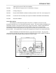
INTRODUCTION Performance The Labconco Protector Controlled Atmosphere Glove Box provides an effective physical barrier between the laboratory and the glove box interior. This barrier system results in three distinct advantages. First, it helps protect the technician from hazardous materials. Secondly, it protects valuable laboratory materials against the effects of ambient air and moisture.
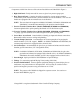
INTRODUCTION Component Identification General components of the glove box are listed below and identified in Figure 2. 1. Glove Ports. Epoxy coated aluminum, 8" I.D. spaced 17 inches apart, sealed to viewing window with one-piece molded neoprene gasket. Supplied with dual O-ring grooves, neoprene gloves, retaining O-rings and clamps. 2. Neoprene Gloves. Supplied with the glove box, gloves are .015" thick neoprene, 30" long, one pair size 9-3/4. Note: For replacement gloves see Replacement Parts, page 44. 3.
INTRODUCTION 13A. Interior Transfer Chamber Door (Models 506010000, 507010000, 508010000). 11 gauge type 304 stainless steel, counterweighted with quick operating latch.
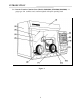
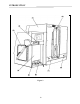
INTRODUCTION Components visible from the rear of the unit are listed below and identified in Figure 3. 1. Right Side Panel. Easily removed for access to glove box pressure gauge port. 2. Rear Electrical Panel. Contains electrical receptacle for vacuum pump operation (controlled by front mounted switch), and two manual reset circuit breakers. The 230 volt models are equipped with one manual reset circuit breakers.
INTRODUCTION Figure 3 10
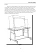
INSTALLATION Location The glove box should be placed on a stable, level base stand equipped with a lower shelf to accommodate a vacuum pump near an electrical receptacle rated at 115V, 60 Hz, 20 amp for 115 volt models, or 230V, 50 Hz, 10 amp for 230 volt models. The base stand must be capable of supporting 500 pounds minimum, and the height should provide a comfortable working position through the glove ports.
INSTALLATION Pressure Relief Bubbler The Pressure Relief Bubbler operates with vacuum pump oil having a specific gravity of 0.87. The user must determine the compatibility of substances used in the glove box with vacuum pump oil. The Pressure Relief Bubbler is designed to relieve positive and negative pressure in the glove box. The relief pressure point is established by the amount of oil that is poured into the bubbler at time of installation.
INSTALLATION 4. Hold the bubbler straight (with the vertical tubes perpendicular to the glove box base) and tighten the top hanger bracket #8 x 1/2" screw. Secure the bubbler to the hanger bracket by tightening the _-20 nut. 5. Remove the pipe plug from the fill spout and fill the bubbler with vacuum pump oil (.87 specific gravity) to the desired pressure relief level (must be less than 10) as indicated on the graduated sight glass (inches H2O). The recommended level is 7 inches for most applications.
INSTALLATION Gas and Vacuum Internal Connections (Models 506000000, 506010000, 507000000 and 507010000) Before making gas and vacuum connections on all models except 508000000 or 508010000, determine if the transfer chamber should be backfilled with gas directly from your inert gas supply tank or from the glove box.
INSTALLATION Gas and Vacuum External Connections All gas and vacuum connections are located on the back of the transfer chamber housing and are clearly labeled as shown in Figure 7. 1. Vacuum Pump Connection. This is a copper tube of 7/8" O.D. on Models 506000000, 506010000, 507000000, and 507010000. On Models 508000000 and 508010000, this is a solenoid valve with 3/4" female pipe connection. Connect to your vacuum pump intake.
INSTALLATION Figure 7 Gas and vacuum connections are illustrated for the various models in Figures 8, 9 and 10. The illustrations show connections for models as follows: Figure 8 depicts Models 506000000 and 506010000, Figure 9 depicts Models 507000000 and 507010000, Figure 10 depicts Models 508000000 and 508010000.
INSTALLATION Models 5060000 and 5060100 Figure 8 1. Electrical Receptacle for Vacuum Pump. Controlled by the “Exterior Outlet” switch on the front panel. 2. Vacuum Connection Kit. Labconco Catalog No. 5060600 or equivalent. 3. Vacuum Pump. Labconco Catalog No. 1467700 (190 liters/minute) or Labconco Catalog No. 1472100 (113 liters/minute) or their equivalents. 4. Connection to Inert Gas Supply. Regulated to 15 – 20 psi. Complete Connection Kit, Vacuum and Gas (includes 5060600). Labconco Catalog No.
INSTALLATION Models 5070000 and 5070100 Figure 9 1. Electrical Receptacle for Vacuum Pump. Automatically controlled by pressure control module. 2. Vacuum Connection Kit. Labconco Catalog No. 5060600. 3. Vacuum Pump. Labconco Catalog No. 1467700 (190 liters/minute) or Catalog No. 1472100 (113 liters/minute) or their equivalents. 4. Connection to Inert Gas Supply. Regulated to 15 – 20 psi. Complete Connection Kit, Vacuum and Gas (includes 5060600). Labconco Catalog No. 5060900.
INSTALLATION Models 5080000 and 5080100 Figure 10 1. Electrical Receptacle for Vacuum Pump. Automatically controlled by pressure control module. 2. Vacuum Connection Kit. Labconco Catalog No. 5060600 or equivalent. 3. Vacuum Pump. Catalog No. 1467700 (190 liters/minute) or Catalog No. 1472100 (113 liters/minute) or their equivalents. 4. Connection to Inert Gas Supply. NOTE: This tubing should be no less than 5/16" inside diameter.
INSTALLATION volume. If smaller, more restrictive tubing is used, the regulator pressure may be increased to 30-40 psi to provide ample flow. Complete Connection Kit, Vacuum and Gas (includes 5060600). Catalog No. 5061100. See Accessories Section, for list of parts provided in kits. Glove Attachment With glove thumbs up and right/left orientation, secure the gloves in place on the glove ports by stretching the beaded glove cuff into the groove nearest the window.
SAFETY PRECAUTIONS The following safety precautions should be regarded when operating the Controlled Atmosphere Glove Box. • This product is neither designed nor intended to be an explosion-proof enclosure. It is the responsibility of the user to determine the lower explosive limits and flammability of the enclosed gases and other matter. The user is also responsible for using proper precautions to prevent equipment damage or injury due to explosion or combustion.
NORMAL OPERATION Start Up • Confirm that the glove box electrical power cord is plugged into a 115 volt, 60 Hz, 20 amp electrical power source (or 230V, 50Hz, 10 amp) as appropriate. • Switch on the fluorescent lamp and check to make sure the bulb is working. Operation of Controls Pressure Control Module (Models 5070000, 5070100, 5080000 and 5080100) A.
NORMAL OPERATION C. The Labconco CA Glove Box is designed to operate in the range of +6 to –6 inches of water pressure (gauge). With such a relatively small amount of pressure/vacuum setting, outside factors can and will alter the working pressures in the box. To overcome these factors, the Pressure Control Module will maintain the desired pressure differential with the surrounding atmosphere.
NORMAL OPERATION Figure 14 24
NORMAL OPERATION Purge/Fill Control Module (Models 5080000 and 5080100) A. To energize the purge/fill automatic control module, actuate the pressure control power switch located on the rear panel to the “ON” position. B. Actuate the exterior outlet switch located on the front control panel to the “AUTO” position.
NORMAL OPERATION Glove Box Valves and Gauge (Models 5060000 and 5060100 with Manual Pressure Control) Positive Pressure Operation (Refer to the diagram below) With the inner door closed and the glove box “gas in” and “gas out” valves closed (valve handles horizontal), open the gas supply tank valve. Then slowly open the “gas in” valve and observe the pressure gauge. When pressure reaches +2 to +3 inches water column, close the valve.
NORMAL OPERATION Transfer Chamber Valves and Gauge (Models 5060000, 5060100, 5070000 and 5070100 with Manual Pressure Control) With inner and outer transfer chamber doors closed and latched and transfer chamber “fill” and “vacuum” valves closed (valves handles horizontal), switch exterior outlet “ON” to start the vacuum pump. Open the vacuum valve and observe the vacuum gauge as the transfer chamber decompresses.
NORMAL OPERATION Transfer Chamber Valves, Gauge and Controls (Models 5080000 and 5080100 with Purge/Fill Control Module) Check to see if the pressure control module is energized and the lighted pressure display is on. If not, turn on the rear panel pressure control power switch and make sure the front panel vacuum pump outlet switch is in the AUTO position. Also make sure both the inner and outer transfer chamber doors are closed and latched. A. To perform an automatic purge/fill sequence. 1.
NORMAL OPERATION “sequence” indicators (the number of cycles selected) will remain lighted until the next purge/fill cycle is started. C. Clear Switch. Actuating this switch prevents the purge/fill cycle form progressing through the entire sequence. The system will advance directly to the last fill cycle and then end the sequence. D. Manual Mode.
NORMAL OPERATION NOTE: Notice that the pressure gauge changes drastically when the gloves are pulled inward or outward. When selecting operating pressure, this must be considered to, ensure operating limits of ± 5" water column are not exceeded. CAUTION: On Models 5060000 and 5060100 all valves must be closed when the glove box is unattended. To further reduce the moisture level, the optional Drying Train (Catalog #50613) may be installed. Transfer Procedure (Models 5060000, 5060100, 5070000 and 5070100: 1.
ROUTINE MAINTENANCE Routine Maintenance Schedule The maintenance required to the glove box is strongly dependent upon the amount of use and the tolerance to leakage. Highly critical or hazardous procedures dictate a more frequent inspection. Establish a schedule and keep a record of maintenance that reasonably satisfies the needs of the piece of equipment. Include in that schedule the following items: Quarterly, or more frequently • • • Check the oil level in the bubbler through the sight glass.
ROUTINE MAINTENANCE • • • • Stretch the new glove’s beaded cuff over the old glove cuff and into the groove nearest the window. To remove the old glove, grasp the new glove surface and manipulate the old glove bead free from the outer groove. With the other glove hand inside the box, pull the old glove into the glove box. Install the O-ring over the new glove onto the outer groove.
ROUTINE MAINTENANCE Checking Door Latch Tension Closing the latch handle should require some firm force, indicating compression of the rubber door seals. Seal compression and latching force can be adjusted as follows: • • First close and latch the door. Then using a _ inch open-end wrench, turn the door adjustment screw (located between the door and the latch bar) clockwise to increase the seal compression and latching force. Turn screw counterclockwise to decrease compressions.
PLUMBING DIAGRAMS Models 5060000 and 5060100 Figure 19 34
PLUMBING DIAGRAMS Models 5070000 and 5070100 Figure 20 35
PLUMBING DIAGRAMS Models 5080000 and 5080100 Figure 21 36
WIRING DIAGRAMS Models 5060000 and 5060100 – 115 VAC, 60 Hz Figure 22 37
WIRING DIAGRAMS Models 5070000 and 5070100 – 115 VAC, 60 Hz Figure 23 38
WIRING DIAGRAMS Models 5080000 and 5080100 – 115 VAC, 60 Hz Figure 24 39
WIRING DIAGRAMS Models 5060000-02 and 5060100-02 – 230 VAC, 50 Hz Figure 25 40
WIRING DIAGRAMS Models 5070000-02 and 5070100-02 – 230 VAC, 50 Hz Figure 26 41
WIRING DIAGRAMS Models 5080000-02 and 5080100-02 – 230 VAC, 50 Hz Figure 27 42
REPLACEMENT PARTS Figure 28 43
REPLACEMENT PARTS Ref. No. Qty. 1 2 3 3A 4 5 6 7 8 9 10 11 12 13 14 15 16 17 18 19 20 21 22 22A 23 23A 24 24A 25 25A 26 26A 27 28 1 1 1 1 1 1 Pr 1 1 Pr 1 1 Pr 1 1 Pr 1 1 Pr 1 1 Pr 1 Pr 1 Pr 1 1 3 1 3 3 1 1 1 1 1 1 1 1 1 1 Catalog No.
REPLACEMENT PARTS Glove Ports Ref. No. 1 2 3 4 Qty. Catalog No. Description 1 1 1 1 5074201 5074301 5066800 1889310 Glove Port Glove Port Mounting Ring Glove Port Gasket Glove Port Mounting Screw Figure 29 Sealed Receptacle Assembly Ref. Qty. Catalog No. No.
REPLACEMENT PARTS Fluorescent Lamp Assembly (Complete with Bulb), No. 5072602 (115V) or No. 5072603 (230V) Ref. No. 1 2 2A 3 Qty. Catalog No.
REPLACEMENT PARTS Inner Door Assembly No. 5067701 (Used on 5060000, 5070000, 5080000 with fiberglass liners) or No. 5098500 (Used on 5060100, 5070100, 5080100 with stainless steel liners). Ref. No. Note: 1 2 3 4 5 6 7 8 9 Catalog No. Catalog No.
REPLACEMENT PARTS Outer Door Assembly No. 5068401 (Used on 5060000, 5070000, 5080000 with fiberglass liners) or No. 5098600 (Used on 5060100, 5070100, 5080100 with stainless steel liners). Ref. No. Note: 1 2 3 4 5 6 7 8 Catalog No. Catalog No.
ACCESSORIES Accessory Part# 5061600 Description 5062000 Glove Box Mobile Stand Welded steel construction, epoxy coated with black phenolic laminate top surface. 1/1/8" thick x 30" D x 60" W, height adjustable from 30 to 37 inches. Lower storage shelf provides convenient space for vacuum pump and optional drying train. Accessory includes 5" swivel casters with locking brakes. 5062001 Glove Box Stand Same as above except furnished with adjustable leveling feet instead of casters.
ACCESSORIES and vacuum pump. It includes the following components: • Neoprene vacuum tubing, 3/4" I.D. x 3/8" wall x 3 ft long • Neoprene vacuum tubing, 3/4" I.D. x 3/8" wall x 12" long • Stainless steel reducing elbow/tee, 7/8" x 7/8" x 3/8" • Vacuum tubing, 5/16" I.D. x 3/16" wall x 6 ft long • Copper tubing, 3/8" O.D. x 12" long, to connect with the Glove Box exhaust Swagelok fitting.
WARRANTY We are committed to providing our customers with quality equipment and service after the sale. Part of this objective involves keeping you informed of changes and new product additions. We, therefore, request that you take a moment to fill out the product registration card so we many know your location as well as some of the reasons that prompted you to purchase our product. Labconco provides a warranty on all parts and factory workmanship.
SHIPPING CLAIMS If a shipment is received in visibly damaged condition, be certain to make a notation on the delivering carrier’s receipt and have their agent confirm the damage on your receipt. Otherwise, the damage claim may be refused. If concealed damage or pilferage is discovered, notify the carrier immediately and retain the entire shipment intact for inspection. Interstate Commerce Commission rules require that the claim be filed with the carrier within 15 days after delivery.
CONTACTING LABCONCO If you have any questions that are not addressed in this manual, or if you need technical assistance, please contact Labconco’s Sales Information Department at 1-800-821-5525, and Service Information at 1-800-522-7658 or 1-816-333-8811, between the hours of 7:00 a.m. and 6:00 p.m. Central Standard Time. Labconco’s mailing address is: Labconco Corporation 8811 Prospect Avenue Kansas City, Missouri 64132-2696 Fax # 816-363-0130 Visit Labconco through the Internet at: http://www.labconco.
54