User’s Manual Protector® ClassMate® Laboratory Fume Hoods Models 69704 Series 69706 Series 69715 Series 69705 Series 69714 Series 69716 Series To receive important product updates, complete your product registration card online at register.labconco.com Labconco Corporation 8811 Prospect Avenue Kansas City, MO 64132-2696 800-821-5525, 816-333-8811 FAX 816-363-0130 E-MAIL labconco@labconco.com HOME PAGE www.labconco.com Please read the User’s Manual before operating the equipment.
Copyright © 2001, 2007 Labconco Corporation. All rights reserved. The information contained in this manual and the accompanying products are copyrighted and all rights reserved by Labconco Corporation. Labconco Corporation reserves the right to make periodic design changes without obligation to notify any person or entity of such change. Warranty Labconco provides a warranty on all parts and factory workmanship.
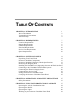
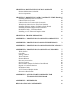
TABLE OF CONTENTS CHAPTER 1: INTRODUCTION About This Manual Typographical Conventions Your Next Step 1 2 3 4 CHAPTER 2: PREREQUISITES Location Requirements Support Requirements Exhaust Requirements Electrical Requirements Service Line Requirements Space Requirements 7 8 8 8 10 10 10 CHAPTER 3: GETTING STARTED 11 Unpacking Your Fume Hood 12 Protector ClassMate Components 13 Protector ClassMate Laboratory Hoods Specifications 13 Removing the Shipping Skid 15 Installing the ClassMate on a Supporting Struct
CHAPTER 6: MAINTAINING YOUR CLASSMATE Routine Maintenance Schedule Service Operations 43 44 45 CHAPTER 7: MODIFYING YOUR CLASSMATE FUME HOOD Installing Additional Service Fixtures Labconco Service Fixture Labconco Service Fixture with Gooseneck WaterSaver Outlet Service Tube Part Numbers Installing Exhaust Adapter for Back to Back Hoods Installing Guardian Digital Airflow Monitor Distillation Grids – Field Installation Installing a 115V Electrical Duplex Outlet 47 47 48 50 52 53 53 57 60 CHAPTER 8: TROU
CHAPTER 1 INTRODUCTION Congratulations on your purchase of a Labconco Protector ClassMate Laboratory Fume Hood. Your Protector ClassMate is designed to protect you. It is the result of Labconco’s more than 50 years experience of manufacturing fume hoods, and users like you suggested many of its features to us.
Chapter 1: Introduction About This Manual This manual is designed to help you learn how to install, use, and maintain your laboratory fume hood. Instructions for installing optional equipment on your hood are also included. Chapter 1: Introduction provides a brief overview of the laboratory fume hood, explains the organization of the manual, and defines the typographical conventions used in the manual.
Chapter 1: Introduction Appendix A: Protector ClassMate Components contains labeled diagrams of all of the components of the fume hoods. Appendix B: Protector ClassMate Dimensions contains comprehensive diagrams showing all of the dimensions for the 4, 5 and 6 foot models of the laboratory fume hoods. Appendix C: Protector ClassMate Specifications contains the electrical requirements for laboratory fume hood. Wiring diagrams are also included.
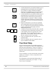
Chapter 1: Introduction • ! • ) 4' 5' 6' S A • • • • Critical information is presented in boldface type in paragraphs that are preceded by the exclamation icon. Failure to comply with the information following an exclamation icon may result in injury to the user or permanent damage to fume hood. Critical information is presented in boldface type in paragraphs that are preceded by the wrench icon. These operations should only be performed by a trained certifier or contractor.
Chapter 1: Introduction If your laboratory fume hood is installed and you need to perform routine maintenance on the cabinet, proceed to Chapter 6: Maintaining Your Protector ClassMate. For information on making modifications to the configuration of your unit, go to Chapter 7: Modifying Your Laboratory Fume Hood. Refer to Chapter 8: Troubleshooting if you are experiencing problems with your Fume Hood.
Chapter 1: Introduction 6 Product Service 1-800-522-7658
CHAPTER 2 PREREQUISITES Before you install your laboratory fume hood, you need to prepare your site for installation. Carefully examine the location where you intend to install your hood. You must be certain that the area is level and of solid construction. In addition, a dedicated source of electrical power must be located near the installation site. Carefully read this chapter to learn: • • • • • • The location requirements for your installation site. The support requirements for your installation site.
Chapter 2: Prerequisites Location Requirements ! The Fume Hood should be located away from traffic patterns, doors, fans, ventilation registers, and any other air-handling device that could disrupt its airflow patterns. All windows in the room should be closed. Support Requirements ! DO NOT locate the fume hood on a cart, dolly, or mobile bench. ALL Protector ClassMate installations must be permanent and stationary.
Chapter 2: Prerequisites Catalog Number Standard Model Description 69704-00 48" Hood without fixtures & duplexes 69704-01 48" Hood with 4 fixtures & 2 duplexes 69705-00 60" Hood without fixtures & duplexes 69705-01 60" Hood with 4 fixtures & 2 duplexes 69706-00 72" Hood without fixtures & duplexes 69706-01 72" Hood with 4 fixtures & 2 duplexes Catalog Number Reduced Air Volume Model Description 69714-00 48" Single Sash Hood without monitor, fixtures & duplexes 69714-01 48" Single Sash Ho
Chapter 2: Prerequisites Electrical Requirements The Protector ClassMate Hood models feature internal wiring for the fluorescent light assembly and light switch. All hood models with 115V, 60 Hz duplex outlets are terminated at the internal boxes for hook-up by a qualified electrician. The blower switch, and light switch wires are also terminated at the internal boxes for hook-up by a qualified electrician.
CHAPTER 3 GETTING STARTED Now that the site for your laboratory fume hood is properly prepared, you are ready to unpack, inspect, install, and certify your unit. Read this chapter to learn how to: • Unpack and move your Protector ClassMate Hood. • Set up the fume hood with the supporting structure and work surface. • Connect to an exhaust system. • Connect the electrical supply source. • Connect the service lines. • Sealing the Protector ClassMate Hood.
Chapter 3: Getting Started people and follow safe-lifting guidelines. Normally, the fume hood can slide off a hydraulic lift and be placed into position on top of the work surface. Unpacking Your Laboratory Fume Hood The United States Interstate Commerce Commission rules require that claims be filed with the delivery carrier within fifteen (15) days of delivery. Carefully remove the shrink-wrap on your fume hood and inspect it for damage that may have occurred in transit.
Chapter 3: Getting Started Protector ClassMate Components Labconco manufactures Protector ClassMate Fume Hoods for operation with vertical rising sashes or combination A-Style sashes. Each of the hoods is available in 4-foot, 5-foot and 6-foot models. Models are all 115V. Locate the hood model you received in the following group of tables. Verify that the components listed are present and undamaged. Protector ClassMate Laboratory Hoods General Specifications for All Models By-pass airflow design.
Chapter 3: Getting Started Catalog # 69704-00 69704-01 69705-00 69705-01 69706-00 69706-01 Hood Description 48" Hood without fixtures & duplexes 48" Hood with 4 fixtures & 2 duplexes 60" Hood without fixtures & duplexes 60" Hood with 4 fixtures & 2 duplexes 72" Hood without fixtures & duplexes 72" Hood with 4 fixtures & 2 duplexes Additional Specifications for Models with Combination A-Style Sashes 4' hoods have a single vertical rising sash; 5' and 6' hoods have combination horizontal sliding/verticalris
Chapter 3: Getting Started Removing the Shipping Skid ) LEAVE THE FUME HOOD ATTACHED TO ITS SHIPPING SKID UNTIL IT IS AS CLOSE TO ITS FINAL LOCATION AS POSSIBLE. MOVE THE UNIT BY USING A SUITABLE FLOOR JACK, OR BY PLACING A FURNITURE DOLLY UNDERDNEATH THE SKID. DO NOT MOVE THE HOOD BY TILTING IT ONTO A HAND TRUCK. After you verify the fume hood components, move your hood to the location where you want to install it. Then, follow the steps listed next to remove the shipping skid from your unit.
Chapter 3: Getting Started Follow the instructions as shown in Figures 3-1, 3-2, and 3-3 3. 4. 1. Remove and discard the cardboard corner posts (Figure 3-1). 2. Remove strap that secures sash. For A-Style combination sashes disassemble from skid and attach to hood per Step 7. Remove the access panels and after removal, save the access panels and hardware for re-attachment.
Chapter 3: Getting Started Install the Protector ClassMate Hood on A Supporting Structure and Work Surface ! The Protector ClassMate is heavy! Use caution when lifting or moving the unit. When installing the Protector ClassMate Fume Hood onto a chemically resistant work surface or benchtop, ensure that the structure can safely support the combined weight of the fume hood and any related equipment.
Chapter 3: Getting Started The following are instructions for mounting a 2 x 4 cross support: 1. Level the base cabinets and the work surface. 2. Scribe a line on the wall or back of the base cabinet to locate the support under the work surface. 3. Mount the support by attaching it to the wall or base cabinet. 4. Place the hood on top of the work surface and cross support. The work surface should be smooth and durable, and made from a chemically resistant epoxy resin.
Chapter 3: Getting Started Figure 3-5 The exhaust connection should be installed by a qualified HVAC contractor.
Chapter 3: Getting Started The exhaust connection on your hood has been designed for 8" nominal pipe (8.62" O.D.) to allow for minimum static pressure loss with proper transport velocities away from the hood. It is acceptable to combine the air from two back to back hoods with a 12" x 8" x 8" dual exhaust adapter that would basically have two 8" nominal exhaust inlets and one 12" (12.00" O.D.) nominal exhaust outlet. See Appendix D: Protector ClassMate Accessories for dual exhaust adapter.
Chapter 3: Getting Started The identification plate, model number, serial number, and electrical connection boxes are accessible from the front of the fume hood by removing the front panel. The remote blower style Protector ClassMate Hood is fully wired internally for 115 Volt, 60 Hz, 15 Amp electrical service. The number of circuits varies depending on the model. The Protector ClassMate Hood models do not feature internal wiring or electrical components excluding the fluorescent light assembly.
Chapter 3: Getting Started The fluorescent light has been mounted outside the top liner panel assembly and is sealed from any vapors used inside the hood structure. To change the fluorescent light bulbs in your hood, you must first remove the front panel from the hood. Next remove the screws holding down the light reflectors. Remove the light reflectors and slide them away temporarily. The fluorescent light assembly is now fully exposed and ready for service.
Chapter 3: Getting Started Figure 3-8 To install the supply tubing, follow these steps: 1. Remove the valve service plate and outlet fitting access covers by loosening their individual screws. The valve body and service areas will now be fully exposed. 2. Ensure that the tubing is ¼ inch outside diameter, soft metal, and that the end has been deburred completely. (See Appendix D Service Fixture Accessories to order 5.5' of supply tubing 48899-00 or 49211-00 gas). 3.
Chapter 3: Getting Started 7. Close the service valve in the Protector ClassMate Fume Hood and then slowly open the shutoff valve on the service line. ! NOTE: Inspect all fittings for leakage. Tighten the tube nut slightly if needed. ! CAUTION: Do not use oxygen with service fixtures as supplied with this hood. Contact Labconco for oxygen fixture information.
Chapter 3: Getting Started walls of the hoods. Materials such as silicone sealants may be used to seal the hood structure. Certifying the Protector ClassMate Fume Hood The combination of your laboratory hood, exhaust ductwork, and exhaust blower enables you flexibility to change the airflow generated across the sash opening on the hood. To determine the actual face velocity through the sash opening, airflow velocity readings will need to be taken.
Chapter 3: Getting Started Your Protector ClassMate Fume Hood has been certified at the factory per ASHRAE 110-1995. In this procedure Labconco tests the “as manufactured” hood for average face velocity readings, smoke visualization, and tracer gas containment readings less than 0.1 part per million (PPM) with a mannequin. For “field use” ASHRAE testing contact Labconco Sales Engineering Team for a certified on-site contractor.
CHAPTER 4 THEORY OF OPERATION AND SAFETY PRECAUTIONS Theory of Operation: The Protector® ClassMate Laboratory Hood is designed to meet the needs of the science instructor. Clear back and sides and taller front viewing window provide enhanced visibility for the instructor conducting chemistry demonstrations or observing students using the hood. The ergonomic inclined front promotes additional visibility into the laboratory.
Chapter 4: Theory of Operation and Safety Precautions behind the front and under the airfoil to help control fluctuations in face velocity, which occur as the sash is closed. The major components in Protector ClassMate Laboratory Hoods are outlined as follows and in Figure 4-1, and Figure 4-1A: 1. Clear, tempered safety glass sides, back and baffle provide maximum visibility. All glass components except sashes are removable for cleaning. Visibility up to 45" on sides and back. 2.
Chapter 4: Theory of Operation and Safety Precautions wired light is serviceable from outside the hood cavity. 11. Low mounted, factory wired light and blower switches are ADA compliant. 12. Ergonomic airfoil allows air to sweep work surface for maximum containment and provide a Patented Clean Sweep™ on the upper surface to provide maximum containment. 13. Low profile trough below airfoil contains spills. The trough is the same depth as the work surface (1.25") and requires no cabinet overhang. 14.
Chapter 4: Theory of Operation and Safety Precautions different heights and still maintain the same visual accessibility. The 4' hoods have a single vertical rising sash; 5' and 6' hoods have combination horizontal sliding/vertical rising sashes. These combination sashes allow the operator to use the hood with sashes either half open vertically or horizontally to conserve energy.
Chapter 4: Theory of Operation and Safety Precautions Figure 4-1 Product Service 1-800-522-7658 31
Chapter 4: Theory of Operation and Safety Precautions Figure 4-1A 32 Product Service 1-800-522-7658
Chapter 4: Theory of Operation and Safety Precautions Safety Precautions ! ) Although the laboratory hood has been engineered to maintain optimum operator safety, caution should always be used while working in the hood. Prior to using the hood, check to make sure that the exhaust blower is operating and that air is entering the hood at the proper velocity of 100 fpm. USE GOOD HOUSEKEEPING IN THE HOOD AT ALL TIMES. CLEAN UP SPILLS IMMEDIATELY.
Chapter 4: Theory of Operation and Safety Precautions BLOCKS ARE LEVEL AND SET IN PLACE. ! Blocking the bottom of the baffle at rear of hood will change the airflow pattern in the hood causing turbulence and possible leakage at the face of the hood. (Don’t store containers or supplies against baffles, as this will affect airflow through the hood). Avoid placing head inside hood. Keep hands out of hood as much as possible. Always work as far back in hood as possible.
Chapter 4: Theory of Operation and Safety Precautions CREATED MAY DRAW FUMES OUT OF THE HOOD. ! The use of heat generating equipment in this hood without the exhaust system operating properly can cause damage to the hood. The Protector ClassMate Laboratory Hood should be certified by a qualified certification technician before its initial use. The hood should be recertified whenever it is relocated, serviced or at least annually thereafter.
Chapter 4: Theory of Operation and Safety Precautions 36 Product Service 1-800-522-7658
CHAPTER 5 USING YOUR PROTECTOR CLASSMATE FUME HOOD Operating the Vertical Rising Sash S Because of the Protector ClassMate's counterbalanced, anti-racking sash mechanism, it will take only a few pounds of force to move the sash up or down, and you can operate the sash smoothly with one or two hands positioned any where along the handle. The vertical rising sash may be raised from a closed to 18" operating height where it bumps the sash stop.
Chapter 5: Using Your Protector ClassMate Fume Hood Figure 5-1 A Operating the A-Style Combination Sash Some hood models have additional energy saving sashes called A-Style Combination Sashes in place of vertical-rising and pivoting sashes. These combination sashes allow the operator to use the hood with sashes either half open horizontally or vertically to conserve energy. The horizontal sashes are used in normal operating mode.
Chapter 5: Using Your Protector ClassMate Fume Hood Figure 5-2 Combination Sash Typical Sash Stop Horizontal Sash Operating the Blower S A Your Protector ClassMate Fume Hood utilizes a remote style blower, which can be activated from the blower switch by turning the blower switch to “ON”. You can validate the hood performance by watching smoke be drawn away from the hood face opening.
Chapter 5: Using Your Protector ClassMate Fume Hood S A Operating the Lights Your Protector ClassMate Fume Hood utilizes a factory wired fluorescent light to illuminate the hood interior. Simply turn the light switch to “ON” to operate (see Figure 5-4). Figure 5-3 Switches NOTE: Blower switch is blank for HOPEC only.
Chapter 5: Using Your Protector ClassMate Fume Hood Working in your Protector ClassMate Fume Hood Planning • Thoroughly understand procedures and equipment required before beginning work. • Arrange for minimal disruptions, such as room traffic or entry into the room while the hood is in use. Start-up • Turn on fluorescent light and hood blower. • Slowly raise the sash. • Check the baffle air slots for obstructions. • Allow the hood to operate unobstructed for 5 minutes.
Chapter 5: Using Your Protector ClassMate Fume Hood • Avoid using techniques or procedures that disrupt the airflow patterns of the hood. Final Purging • Upon completion of work, the hood should be allowed to operate for two to three minutes undisturbed, to purge airborne contaminants from the work area. Unloading Materials and Equipment • Objects in contact with contaminated material should be surface decontaminated before removal from the hood.
CHAPTER 6 MAINTAINING YOUR PROTECTOR CLASSMATE FUME HOOD Now that you have an understanding of how to work in the fume hood, we will review the suggested maintenance schedule and the common service operations necessary to maintain your fume hood for peak performance. ! Only trained and experienced certification technicians should perform some of the service operations after the fume hood has been properly decontaminated. DO NOT attempt to perform these operations if you are not properly trained.
Chapter 6: Maintaining Your Protector ClassMate Fume Hood Routine Maintenance Schedule Weekly • Using ordinary dish soap to clean the surface inside of the fume hood, and the work surface. • Using an appropriate glass cleaner, clean the sash and all glass surfaces. • Operate the fume hood blower, noting the airflow velocity through the hood using a source of visible smoke.
Chapter 6: Maintaining Your Protector ClassMate Fume Hood Service Operations Front Panel Removal: 1. Simply lift the front panel up and then away from the hood to provide access to the top.
Chapter 6: Maintaining Your Protector ClassMate Fume Hood Changing the Fluorescent Lamp: 4' 5' 6' 1. Turn light switch to “OFF”. 2. Remove the front panel as noted earlier. 3. Reach over the front header of the hood and loosen screws to the light reflector and remove light reflector. 4. Remove the fluorescent lamp by pushing it out of the spring-loaded lamp socket and swinging it out of the other lamp socket. 5. Install the new lamp by reversing the removal procedure.
CHAPTER 7 MODIFYING YOUR PROTECTOR CLASSMATE FUME HOOD There are several ways to modify the fume hood for your individual requirements. These include the addition of service fixtures, exhaust adapter, air monitor, distillation grids, and electrical duplex outlets. See Appendix D: Protector ClassMate Accessories to order. Installing Additional Service Fixtures Additional service fixtures can be installed in the four available service fixture holes in both side walls.
Chapter 7: Modifying Your Protector ClassMate Fume Hood ! If the service line pressure exceeds 40 PSI, it must be equipped with a pressure regulator to reduce the line pressure. Please use the appropriate instructions for the appropriate valves. See Appendix D: Protector ClassMate Accessories to order. Labconco Service Fixture 1. Decide the locations (either position 1 or 3) you want to install the service fixture and outlet fitting and remove the hole plugs, and access panels. (See Figure 7-1) 2.
Chapter 7: Modifying Your Protector ClassMate Fume Hood more turn using pliers or a 9/16" wrench. Note the flow direction on the valve. Following is a list of Labconco Outlet Service Tube Part Numbers: Part Number 69945-00 69945-01 69945-02 69945-03 69946-00 69946-01 69946-02 69946-03 69846-00 Location Front Right Front Left Front Right (Gas) Front Left (Gas) Rear Right Rear Left Rear Right (Gas) Rear Left (Gas) Rear Gooseneck Only Position 1 1 1 1 3 3 3 3 3 6.
Chapter 7: Modifying Your Protector ClassMate Fume Hood Labconco Service Fixture with Gooseneck Use the instructions above for the Labconco Service Fixture except Steps 3 and 4 use the following: 3a. (Gooseneck only) Mount the gooseneck outlet fitting P/N 6983705 on the sidewall through the 3/4" diameter hole and tighten the supplied nut and washer. 3b. (Gooseneck only) Mount the 3/8" female and 3/8" male street elbow P/N 1402400 to the gooseneck outlet fitting.
Chapter 7: Modifying Your Protector ClassMate Fume Hood 2. Mount the WaterSaver valve, listed below, through the 1.25" diameter hole and tighten the supplied round locking ring. Part Number 69837-00 69837-01 69837-02 69837-03 69837-04 Description WaterSaver rigid gooseneck and valve WaterSaver (VAC) Connector and valve WaterSaver (AIR) Connector and valve WaterSaver (GAS) Connector and valve WaterSaver Swivel Gooseneck and valve 3.
Chapter 7: Modifying Your Protector ClassMate Fume Hood Watersaver Outlet Service Tube Part Numbers Part Number 6991300 6991301 6991400 6991401 6991400 Location Front Front (Gas) Rear Rear (Gas) Rear Gooseneck Only Position 1 1 3 3 3 9.
Chapter 7: Modifying Your Protector ClassMate Fume Hood Installing Exhaust Adapter for Back to Back Hoods The common exhaust adapter P/N 6987000 allows you to duct two back-to-back Protector ClassMate Fume Hoods from two 8" (8.62" O.D. pipe) exhaust stacks to one 12" (12.00" O.D. pipe) exhaust stack. (See Figure 7-3) Step 1. Simply place the adapter on both hood exhausts and seal with silicone sealant. Step 2. Attach the 12" (12.00" O.D.) pipe to your blower exhaust.
Chapter 7: Modifying Your Protector ClassMate Fume Hood Tools Required: 1. 2. 3. 4. Power Drill Drill bit size #37 (0.104") 33/64" diameter hole saw Reciprocating saw with saw blades for cutting sheet metal 5. Pilot drill sized to fit the saw blade 6. Phillips head screwdriver with #1 point 7. Slotted screwdriver with 3/32 blade width ! DANGER: Always wear eye protection when using power tools. Observe all necessary precautions when installing or repairing monitors near electrical equipment.
Chapter 7: Modifying Your Protector ClassMate Fume Hood typical size required for a single switch electrical box. If the cardboard template is not available, a dimensioned pictorial is at the back of the manual included with the monitor. Step 2: Using the template, mark off the 3" high by 2" wide hole necessary to clear the rear enclosure portion of the monitor. Mark off the two mounting screw hole locations. Step 3: Drill a pilot hole in each of the four corners. Use the saw to cut out the hole.
Chapter 7: Modifying Your Protector ClassMate Fume Hood Step 8: Place the right angle manifold P/N 6977000 on the back of the monitor so that the exit from the manifold faces the open slot on the right side vertical support of the fume hood. Secure the manifold to the monitor with silicone sealant P/N 1579100. (See Figure 7-5) Step 9: With the manifold exit facing the open slot insert the .50" diameter barbed hose stem P/N 1548101 into the manifold and secure with silicone sealant P/N 1579100.
Chapter 7: Modifying Your Protector ClassMate Fume Hood when the blower and light switches are turned “ON”. (See Figure 7-6) Step 15: The installation of the monitor is now complete. Step 16: Refer to the air monitor manual for calibration, programming, and set-up.
Chapter 7: Modifying Your Protector ClassMate Fume Hood Figure 7-7 Figure 7-8 58 Product Service 1-800-522-7658
Chapter 7: Modifying Your Protector ClassMate Fume Hood 1. Remove the hole plugs and install the grommets into the upper baffle. 2. The vertical rods can now be systematically installed in front of the horizontal rods. The bottom of the rods slip into the footplates which rest on the work surface. Tighten the clamping screws on the footplates. For support you need to drill .147 diameter pilot holes and mount the footplates that rest on the work surface.
Chapter 7: Modifying Your Protector ClassMate Fume Hood Installing a 115V Electrical Duplex Outlet Your Protector ClassMate Fume Hood can be ordered with duplex outlets, however, if you ordered a model without a 115V electrical duplex outlet you can have one installed in the field by a qualified electrician. Figure 7-9 Order the following parts from Labconco to field install a 115V electrical duplex outlet assembly. Parts Required: Qty Part No. 1 ea. 6982400 1 ea. 1885608 1 ea. 1230700 1 ea. 4922401 2 ea.
Chapter 7: Modifying Your Protector ClassMate Fume Hood Step 1: Remove the gray blank wall plate from the hood corner. It is attached to the hood with silicone sealant. You will probably damage the blank wall plate upon removal. Step 2: Remove the 2 x 4 handy box cover on the top of the fume hood from the nearest junction box to the front. Step 3: Install the cable connectors on the junction box, one for inlet power, and one for outlet power.
Chapter 7: Modifying Your Protector ClassMate Fume Hood 62 Product Service 1-800-522-7658
CHAPTER 8 TROUBLESHOOTING Refer to the following table if your fume hood fails to operate properly. If the suggested corrective actions do not solve your problem, contact Labconco for additional assistance. PROBLEM CAUSE CORRECTIVE ACTION Remote blower and lights won’t turn on Wires not connected at junction boxes or switches. Check connection of switches. Check connection to control box on top of unit.
Chapter 8: Troubleshooting PROBLEM CAUSE CORRECTIVE ACTION Fume Hood blower turns on but lights don’t work (cont.) Lamp wiring is disconnected. Inspect lamp wiring. Defective lamp ballasts. Replace lamp ballasts. Improper technique or procedure for the fume hood. See “Certifying the Hood Chapter 3 and “Safety Precautions” Chapter 4 sections in the manual. Restriction of the baffle air slots or – blockage of the exhaust outlet.
Chapter 8: Troubleshooting PROBLEM Electrical duplex outlets no longer have power Service valves no longer operate CAUSE CORRECTIVE ACTION Vertical sash frame is crooked. Place horizontal glass symmetrically and pull sash down to airfoil to realign. Cable is frayed or has slipped off the pulleys. Re-install cable or replace if damaged. Wires not connected or faulty duplex. Check wire connection or replace duplex. Circuit breakers tripped in building electrical supply. Reset circuit breakers.
Chapter 8: Troubleshooting 66 Product Service 1-800-522-7658
APPENDIX A PROTECTOR CLASSMATE COMPONENTS Illustrations A-1 and A-2 indicate the location of the following service parts: Protector ClassMate Replacement Parts Item Quantity Part No.
Appendix A: Protector ClassMate Components 68 Item Quantity Part No.
Appendix A: Protector ClassMate Components Figure A-1 Product Service 1-800-522-7658 69
Appendix A: Protector ClassMate Components Figure A-2 70 Product Service 1-800-522-7658
APPENDIX B PROTECTOR CLASSMATE DIMENSIONS Standard Education Hood Product Service 1-800-522-7658 71
Appendix B: Protector ClassMate Dimensions A-Style Combo Educational Hood Back-to-Back with Work Surface and Cabinets 72 Product Service 1-800-522-7658
APPENDIX C PROTECTOR CLASSMATE FUME HOOD SPECIFICATIONS Electrical Data Cabinet Model 6970400, 6970401 6970500, 6970501 6970600, 6970601 Electrical Requirements 115 VAC – 60 Hz, 1 Phase – 12 Amps 115 VAC – 60 Hz, 1 Phase – 12 Amps 115 VAC – 60 Hz, 1 Phase – 16 Amps 6971400, 6971401 6971500, 6971501 6971600, 6971601 115 VAC – 60 Hz, 1 Phase – 16 Amps 115 VAC – 60 Hz, 1 Phase – 16 Amps 115 VAC – 60 Hz, 1 Phase – 16 Amps Environmental Conditions • • • • • Indoor use only.
Appendix C: Protector ClassMate Specifications • • 74 Transient over-voltages according to Installation Categories II (Over-voltage Categories per IEC 1010). Temporary voltage spikes on the AC input line that may be as high as 1500V for 115V models and 2500V for 230V models are allowed. Used in an environment of Pollution degrees 2 (i.e., where normally only non-conductive atmospheres are present).
Appendix C: Protector ClassMate Specifications Product Service 1-800-522-7658 75
Appendix C: Protector ClassMate Specifications 76 Product Service 1-800-522-7658
APPENDIX D PROTECTOR CLASSMATE FUME HOOD ACCESSORIES S Work Surfaces A The solid epoxy work surfaces are 1.25" thick and are dished to contain a primary spill. The work surface rests on the storage cabinets and the fume hood rests on the work surface. The work surface rests immediately behind the secondary spill trough provided on all Protector ClassMate Fume Hood models.
Appendix D: Protector ClassMate Accessories S A Cupsinks The cupsinks are ordered separately if required for your work surface. Catalog # 4005200 S A Description Durcon CS-4, 3 x 6 Oval Cupsink Storage Cabinets Labconco manufactures four types of Storage Cabinets – Acid, Solvent, Standard Base, and Vacuum Pump. Protector® Acid Storage Cabinets have been engineered to efficiently store and ventilate corrosive materials and include an interior plastic liner to protect the metal from corrosion.
Appendix D: Protector ClassMate Accessories Size/Description 48" 36" 30" 24" 18" 12" 48" w/Self Closing Doors 36" w/Self Closing Doors 30" w/Self Closing Doors 24" w/Self Closing Doors 24" ADA 24" ADA w/Self Closing Doors 18" ADA 12" ADA Size/Description 48" 36" 30" 24" 18" 12" 48" w/Self Closing Doors 36" w/Self Closing Doors 30" w/Self Closing Doors 24" w/Self Closing Doors 24" ADA 24" ADA w/Self Closing Doors 18" ADA 12" ADA Dual Doors 9902000 9902100 9902200 9903000 9903100 9903200 - SOLVENT Right Hi
Appendix D: Protector ClassMate Accessories S A Ductwork and Accessories Labconco supplies a full line of ductwork, couplings, elbows, dampers, T-connectors, Y-connectors, reducers, and zero pressure weather caps. Consult Labconco Sales Engineering Team to request the blower brochure, which has the ductwork accessories or if you need help with selection. S A Service Fixtures Your Protector ClassMate Fume Hood is equipped to mount up to four service fixtures, two per side.
Appendix D: Protector ClassMate Accessories Catalog # 9743203 Description Guardian Digital 335 Airflow Monitor See Chapter 7: “Installing Guardian Digital Monitor” for installation. Distillation Grids S A S A S A The distillation grids allow the hood user to mount motors, stirrers, and other apparatus’.
Appendix D: Protector ClassMate Accessories 82 Product Service 1-800-522-7658
APPENDIX E QUICK CHART FOR PROTECTOR CLASSMATE FUME HOOD Model Number Model Description Sash Type Operating Sash Height (in) Operating Sash Width (in) Total Open Area (Sq. Ft.
Appendix E: Quick Chart for the Protector ClassMate 84 Product Service 1-800-522-7658
APPENDIX F REFERENCES Many excellent reference texts and booklets are currently available. The following is a brief listing: Laboratory Ventilation Standards Federal Register 29 CFR Part 1910 Non-mandatory recommendations from “Prudent Practices”. • Fume hoods should have a continuous monitoring device • Face velocities should be between 60-100 linear feet per minute (lfpm) • Average 2.5 linear feet of hood space per person Occupational Health and Safety U.S. Department of Labor 200 Constitution Avenue N.W.
Appendix F: References ASHRAE 110-1995 Method of Testing Performance of Fume Hoods Evaluates fume hood’s containment characteristics • Three part test: Smoke generation, Face velocity profile, Tracer gas release @ 4 liters per minute • Rated As Manufactured (AM), As Installed (AI) and As Used (AU) American Society of Heating, Refrigerating, and Air Conditioning Engineers 1791 Tullie Circle N.E. Atlanta, GA 30329 (404) 636-8400 ANSI Z9.5-1993 Laboratory Standard Covers entire laboratory ventilation system.
Appendix F: References NFPA 30 – 2000 Flammable and Combustible Liquids Code • Approved cabinets may be metal or wood • Vent location on cabinets are required • Venting of cabinets not a requirement National Fire Protection Association 1 Batterymarch Park P.O. Box 9101 Quincy, MA 02269-9101 (800) 344-3555 General References American Conference of Governmental Industrial Hygienists.Industrial Ventilation, A Manual of Recommended Practice, Cincinnati, OH: 1995. ASHRAE Standard Committee.
Appendix F: References Schilt, Alfred A. Perchloric Acid and Perchlorates. The G. Frederick Smith Chemical Company, Columbus, OH: 1979. Steere, Norman. CRC Handbook of Laboratory Safety, 2nd Edition. CRC Press, 1971.
DECLARATION OF CONFORMITY Application Council Directive(s): 73/23/EEC, 89/336/EEC, 2002/95/EC (ROHS), 2002/96/EC (WEEE), 2004/108/EC Standard(s) to which conformity is declared: EN61010-1, EN61326-1, EN55022, EN61000-3-2/3 Manufacturer’s Name: Labconco Corporation Manufacturer’s Address: 8811 Prospect Avenue Kansas City, MO 64132 USA Importer’s Name: See Shipping/Customs Documents Importer’s Address: See Shipping/Customs Documents for your equipment Type of Equipment: Laboratory Equipment - Educa