User’s Manual Precise® Controlled Atmosphere Glove Boxes and Precise® Basic Glove Boxes CA Models 5220100 5220120 5220121 5220130 5220131 Voltage, Frequency 115V, 60 Hz 230V, 50 Hz 230V, 60 Hz 100V, 50 Hz 100V, 60 Hz Basic Models 5220000 5220020 5220021 5220030 5220031 Voltage, Frequency 115V, 60 Hz 230V, 50 Hz 230V, 60 Hz 100V, 50 Hz 100V, 60 Hz To receive important product updates, complete your product registration card online at register.labconco.
Copyright © 2007, 2008 Labconco Corporation. All rights reserved. The information contained in this manual and the accompanying products are copyrighted and all rights reserved by Labconco Corporation. Labconco Corporation reserves the right to make periodic design changes without obligation to notify any person or entity of such change. Warranty Labconco provides a warranty on all parts and factory workmanship.
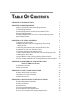
TABLE OF CONTENTS CHAPTER 1: INTRODUCTION 1 CHAPTER 2: PREREQUISITES Support, Vibration & Preventive Requirements Location Requirements Exhaust Requirements for the Pressure Relief Valve Electrical Requirements Plumbing Requirements for Gas, Vacuum, & Drying Train Space Requirements 2 3 3 3 4 4 5 CHAPTER 3: GETTING STARTED Unpacking the Glove Box Installing the Glove Box on a Supporting Structure & Work Surface Connecting the Exhaust to the Pressure Relief Valve Installation of Gloves to the Glove Ports
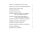
CHAPTER 7: ACCESSORIZING YOUR GLOVE BOX 35 CHAPTER 8: ELECTRICAL SYSTEM TROUBLESHOOTING 42 APPENDIX A: REPLACEMENT PARTS 43 APPENDIX B: DIMENSIONS 45 APPENDIX C: SPECIFICATIONS 46 APPENDIX D: PRECISE CONTROLLED ATMOSPHERE PURGE & FILL REDUCTION RATES 47 APPENDIX E: LIFE SPAN FOR OXYGEN REMOVAL COLUMN & MOISTURE TRAP REMOVAL 49 APPENDIX F: IONIZER FAN PERFORMANCE CRITERIA 51 APPENDIX G: HELIUM LEAK TEST METHOD 53 APPENDIX H: PLUMBING DIAMGRAMS 55 APPENDIX I: PRESSURE & FLOW RATE CONVERSIO
Chapter 1: Introduction Congratulations on your purchase of a Labconco Precise® Controlled Atmosphere Glove Box or Precise® Basic Glove Box manufactured with a one-piece molded polyethylene liner. The Precise Controlled Atmosphere Glove Box comes equipped with six valves, pressure relief valve and two chamber pressure gauge indicators, which are omitted from the Precise Basic Glove Box.
Chapter 2: Prerequisites Before you install the glove box, you need to prepare your site for installation. You must be certain that the area is level and of solid construction. In addition, a dedicated source of electrical power should be located near the installation site to power the glove box. Additionally, the glove box should be strategically placed in the lab to provide efficient workflow and prevent operator interference from normal traffic flow.
Chapter 2: Prerequisites Support, Vibration and Preventive Requirements In the preparation of a glove box site, please consider the following: • A bench or stand that is rigidly mounted to the floor or fixed to the wall, but not both, may be appropriate. 35" to 40" (889mm to 1,016mm) is typical for standing height (Labconco stands offered in Chapter 7 vary from 33" to 40" or 838mm to 1,016mm).
Chapter 2: Prerequisites The first option for venting the pressure relief valve is for ducting unfiltered air to the outside via a 4" nominal diameter exhaust duct. The second and third options for venting the pressure relief valve will add HEPA filters and/or carbon filters to the exhaust duct and allow the vented air back into the laboratory or to the outside. The HEPA filtered and carbon filtered pressure relief vent kits may be combined if so desired.
Chapter 2: Prerequisites optional drying train removal traps. The two valves on the transfer chamber are used for gas inlet and vacuum outlet lines. The transfer chamber lines can be connected together with the main chamber gas inlet and vacuum outlet lines to simplify gas and vacuum connections to both chambers. Illustrations for all gas, vacuum, and recirculating drying trains are shown in Figures 3-5 through 3-10 in Chapter 3. All valves utilize 3/8" (9.5mm) compression fittings or 3/8" (9.
Chapter 3: Getting Started Once the site for your glove box is properly prepared, you are ready to unpack, inspect, install, and validate performance of your system. Read this chapter to learn how to: • Unpack and move the glove box. • Set up the glove box with the proper supporting structure and work surface. • Connect an exhaust system to the pressure relief valve (if applicable). • Install the gloves. • Connect the electrical supply.
Chapter 3: Getting Started Lifting Instructions Unpacking the Glove Box We recommend that you do not remove the glove box from its shipping container until it is ready to be placed into its final location. Move the unit by placing a flat, low dolly under the shipping skid, or by using a floor jack. Carefully remove the shrink-wrap and carton on the glove box and inspect it for damage that may have occurred in transit.
Chapter 3: Getting Started ) IF ENCLOSURE WAS DAMAGED IN TRANSIT, YOU MUST FILE A CLAIM DIRECTLY WITH THE FREIGHT CARRIER. LABCONCO CORPORATION AND ITS DEALERS ARE NOT RESPONSIBLE FOR SHIPPING DAMAGES. Do not discard the packing material until you have checked all of the components and tested the glove box. Installing the Glove Box on a Supporting Structure and Work Surface Exercise caution when lifting or moving the glove box.
Chapter 3: Getting Started To connect the Pressure Relief Vent Valve to an exterior exhaust system, order the Ventilation Kit (#5242700) and refer to Figure 3-1. To provide HEPA filtered exhaust to the room or outside, order the HEPA Filtered Pressure Relief Vent Kit (#5238500) and refer to Figure 3-2. To provide carbon filtered exhaust to the room or outside, order the Carbon Filtered Pressure Relief Vent Kit (#5241200) and refer to Figure 3-3.
Chapter 3: Getting Started Figure 3-1 Pressure Relief Vent Kit (#5242700) 10 Product Service 1-800-522-7658
Chapter 3: Getting Started Figure 3-2 HEPA Filtered Pressure Relief Vent Kit (#5238500) Product Service 1-800-522-7658 11
Chapter 3: Getting Started Figure 3-3 Carbon Filtered Pressure Relief Vent Kit (#5241200) 12 Product Service 1-800-522-7658
Chapter 3: Getting Started Installation of Gloves to the Glove Ports With the thumbs up and in a right/left orientation, secure the gloves in place on the glove ports by stretching the beaded glove cuff into the glove port groove nearest the window. Install the separate 8" diameter O-ring over the gloves, into the outer groove of the glove port surface. Stainless steel band clamps are provided for securing the separate O-ring into the glove port groove. Replacement gloves and parts are listed in Chapter 7.
Chapter 3: Getting Started Connect the Plumbing Lines for Gas, Vacuum, and Drying Train Labconco offers various vacuum and gas tubing installation kits listed in Chapter 7 for connecting gas and vacuum line, or drying train to the glove box. Refer to Figures 3-6, 3-7, 3-8, 3-9, and 3-10 that depict the installation tubing kits. The primary connecting method involves the use of 3/8" O.D. x 3/16" I.D.
Chapter 3: Getting Started B Hose Connector Small Ferrule Alternative Method with Hose Connector Compression Nut Note: Hose Clamp not supplied.
Chapter 3: Getting Started Figure 3-6 Typical Tubing Connections for Manual Valve Operation (Tubing Connection Kit 5245100 provides full details) 16 Product Service 1-800-522-7658
Chapter 3: Getting Started Figure 3-7 Typical Tubing Connections with Automatic Pressure Controller (Tubing Connection Kit 5245200 provides full details) Product Service 1-800-522-7658 17
Chapter 3: Getting Started Figure 3-8 Typical Connections Shown with Connection to the Automatic Pressure Controller (Full details provided with Automatic Pressure Controller) 18 Product Service 1-800-522-7658
Chapter 3: Getting Started Figure 3-9 Typical Tubing Connections for Oxygen & Moisture Removal Shown with the Automatic Pressure Controller (Tubing Connection Kit 5242501 provides full details) Product Service 1-800-522-7658 19
Chapter 3: Getting Started Figure 3-10 Typical Tubing Connections for Dual Moisture/Solvent Removal System Shown with the Automatic Pressure Controller (Tubing Connection Kit 5242500 provides full details) Validating the Glove Box Each Precise Glove Box has been helium leak tested at the factory for integrity and found to have no leaks greater than 1 x 10⁻⁴ cc/sec while at a positive pressure of 5 inches helium. Refer to Chapter 6, Initial Certification and Appendix G for Helium Leak Test Method.
Chapter 3: Getting Started chambers. Figure 3-11 shows test results of the oxygen decay or oxygen level increase as a function of time. Per ISO specifications, Class 1 controlled atmosphere chambers have a specified hourly leak rate of less than 5 x 10⁻⁴ per Table 3-1 listed at the end of Chapter 3. Precise CA Glove Box Oxygen Decay Leak ISO 10648-2 Test Method 140 Oxygen Decay 120 Barometic Pressure: 28.66 inches of Hg 100 Time Minutes Main Chamber Temp.: 77.
Chapter 3: Getting Started Table 3-1 Classification of Glove Box Containment per ISO 10648-2 Class Hourly Leak Rate (Tf) 1 2 ≤ 5 x 10⁻⁴ hr-1 < 2.
Chapter 3: Getting Started Pressure Change Leak Testing Method Summary (ISO-10648-2) The method consists of measuring the pressure rise per unit time after establishing a negative pressure in the main chamber of the glove box. Use -1000 Pa for the acceptance test and -250 Pa for the operational test. The hourly leak rate includes adjustments for barometric pressure and temperature changes which can be calculated as Tf: Tf = (60/t) * ((PnT1/P1Tn) -1) where t is the duration of the test in minutes.
Chapter 4: Performance Features and Safety Precautions Performance Features The Precise Controlled Atmosphere Glove Box comes fully equipped with six valves, pressure relief valve, and two pressure gauges. The Precise Controlled Atmosphere Glove Box is designed to meet the needs of the laboratory scientists requiring an inert atmosphere for sensitive ambient air operations. Labconco has engineered the Precise Controlled Atmosphere Glove Boxes to meet the ISO 10648-2 Class 1 atmosphere leak specification.
Chapter 4: Performance Features and Safety Precautions Generally, 75-100 purge and fill cycles are required to reduce moisture and oxygen levels below 1% (see Appendix D). 100-150 purge and fill cycles will typically reduce moisture and oxygen levels to 0.3% or 3,000 ppm. After a 1% or less moisture and oxygen level is achieved, the other two valves on the main chamber can be opened when they are connected to a recirculating moisture and/or oxygen removal system.
Chapter 4: Performance Features and Safety Precautions 11. Interior Switched Duplex is located on the glove box ceiling. The innermost outlet of the duplex labeled “AUX” is controlled by the switch located on the front control panel. The other outlet is on constantly when the glove box is connected to an electrical supply. An accessory Electrical Power Strip can be connected to the outlet to provide more electrical receptacles (see Chapter 7).
Chapter 4: Performance Features and Safety Precautions Safety Precautions 1. It is the responsibility of the user to determine the suitability of this product for the intended applications. Consult your Safety Officer for application review. 2. Although the glove box has been engineered to maintain optimum operator safety, caution should always be used while working. Prior to using the glove box, check to make sure that the main chamber pressure is set for comfortable glove manipulation.
Chapter 4: Performance Features and Safety Precautions 12. All powders, gases, and particulates removed by the operation of the vacuum pumps connected to this glove box are to be filtered and/or ducted to the outside. 13. Exhaust vacuum pumps should be filtered and/or ducted to the outside when using hazardous materials. Consult your Safety Officer.
Chapter 5: Using Your Glove Box Now that the installation of your glove box is completed, you are ready to use it. Read this chapter to learn about: • Routine Daily Work Procedures. • Hazardous Use with Chemicals. • Prohibited Acid Use. Routine Daily Work Procedures Planning • Thoroughly understand procedures and equipment required before beginning work. Work from a written plan. • Arrange for minimal disruptions, while the glove box is in use.
Chapter 5: Using Your Glove Box • Perform purge and fill cycle on the transfer chamber using the vacuum outlet and gas inlet valves. Depending on the vacuum level achieved, it takes 1-5 cycles to reduce oxygen and moisture levels below 1%. Porous materials being transferred may require longer sustained vacuum purges to remove the oxygen and moisture trapped in the materials.
Chapter 5: Using Your Glove Box • Objects in contact with previously contaminated internal atmospheres must be surface decontaminated or bagged before removal from the glove box through the transfer chamber. • After placing materials to be removed in the transfer chamber and locking the internal door, the transfer chamber must be purged and filled approximately 1-5 times depending on vacuum level achieved. This ensures the removal of any remaining airborne contaminants before the outer door is opened.
Chapter 6: Maintaining Your Glove Box Review this chapter on maintenance for the following: 1. 2. 3. 4. 5. 6. Routine maintenance. Initial certification. Recertification. Fluorescent light replacement. Pressure relief valve replacement. Service valve and pressure gauge replacement. Routine Maintenance Schedule Weekly • Wipe down the interior surfaces of the glove box with a disinfectant or cleaner, depending upon the application.
Chapter 6: Maintaining Your Glove Box Initial Certification Each Precise Glove Box has been leak tested at the factory with helium gas at positive 5" w.g. pressure; no leaks greater than 1 x 10⁻⁴ cc/sec are allowable. The glove box should be certified by your Safety Officer before use, with one of the two tests listed below under Recertification. See Appendix G for Labconco Helium Leak Test Method performed on all glove boxes at the factory.
Chapter 6: Maintaining Your Glove Box 7. Install the new pressure relief valve with the gasket to the inside. Tighten the large nut. 8. Turn the glove box ON and re-certify the glove box. 9. Refer to Appendix A, Appendix B and Chapters 3 and 7 for installation diagrams. Service Valve and Pressure Gauge Replacement 1. Decontaminate the glove box interior, if required. 2. Wear appropriate protective equipment as determined by your Safety Officer. 3. Turn the glove box and vacuum pump OFF. 4.
Chapter 7: Accessorizing Your Glove Box There are many ways to accessorize and modify the controlled atmosphere glove box for your individual requirements. These include many different accessories listed in this chapter. 1. Black Epoxy Flat Work Surface (Part #4882807) A solid epoxy resin 60" x 30" x 1.25" work surface is available to support the glove box. 2. 30" Standard Base Cabinet (Part #9900200) Two optional base cabinets can be ordered to support the 60" x 30" work surface and glove box.
Chapter 7: Accessorizing Your Glove Box separately. This kit can be used if additional valves are desired or valves are added to the Precise Basic Glove Box. For a complete installation of six valves, mounting brackets, pressure relief valve, and labels for the Precise Basic Glove Box, order Full Valve Kit #5232101. All valves require a 0.688" (17.5mm) diameter hole to be drilled for mounting. 7.
Chapter 7: Accessorizing Your Glove Box Figure 7-1 All dimensions in inches 11. Pressure Relief Vent Kits and Pressure Relief Valve Pressure relief vent kits are detailed in Chapters 2 and 3 and include tubing connections and/or filters. Three pressure relief vent kits are available to vent either unfiltered air or filtered air. All pressure relief vent kits include a 3.9" (99mm) OD x 3.8" (97mm) ID nominal thimble for connection to a house exhaust.
Chapter 7: Accessorizing Your Glove Box 13. Automatic Pressure Controller The Pressure Controller allows the end user the convenience of automatically regulating pressure and vacuum within the glove box main chamber and transfer chamber. The end user can also automate the purge/fill cycles up to 199 cycles for each chamber. The vacuum and pressure can be automatically regulated between -5 to +5 inches of water gauge in the main chamber and between 0 to -29 inches of mercury gauge in the transfer chamber.
Chapter 7: Accessorizing Your Glove Box 14. Filtration Components for Moisture, Oxygen and Fume Removal The following components can be used to remove organics, acids, ammonia, oxygen, moisture and other gases as indicated. They are connected to the two auxiliary valves on the main glove box chamber for recirculation of main chamber atmosphere and contaminant removal of air (see Figures 3-9 and 3-10).
Chapter 7: Accessorizing Your Glove Box 18. Moisture Monitors/Hygrometers Moisture monitors or hygrometers allow the user to continuously monitor moisture levels inside the glove box. All moisture monitors are placed inside the main chamber. Never operate a transfer chamber vacuum purge on these sensitive hygrometers as damage can occur.
Chapter 7: Accessorizing Your Glove Box 24. IV Bar Kit (Part #5242100) Provides a bar for hanging IV bags or tools. Must be used with one of the interior storage shelf kits (5235000 or 5235001). 25. Gloves (see Appendix A: Replacement Part numbers for other glove sizes and material types) Neoprene gloves are the most resistant to abrasion and tearing. Butyl gloves provide higher impermeability and improved dexterity.
Chapter 8: Electrical System Troubleshooting Refer to the following table if your glove box fails to operate properly. If the suggested corrective actions do not solve your problem, contact Labconco for additional assistance. The Precise Controlled Atmosphere Glove Box and Precise Basic Glove Box have only two electrical circuits. PROBLEM CAUSE CORRECTIVE ACTION Lights won’t operate. Unit not plugged into outlet. Plug unit into appropriate electrical service. Circuit breaker(s) tripped.
Appendix A: Replacement Parts The components that are available for your glove box are listed. The parts shown are the most commonly requested. If other parts are required, please contact Product Service. Item Qty.
Appendix A: Replacement Parts Figure A-1 Replacement Parts for Precise Glove Boxes (Precise Controlled Atmosphere Glove Box Shown) 44 Product Service 1-800-522-7658
Appendix B: Dimensions See the following dimensions for all the glove boxes. Precise Controlled Atmosphere shown. All dimensions in inches. Figure B-1 Note: Six valves, pressure relief valve, and two pressure gauges are omitted on the Precise Basic Glove Box.
Appendix C: Specifications This Appendix contains technical information about all the glove boxes including electrical specifications and environmental operating conditions. • 8 Amps, 115V or 4 Amps, 230V, 50/60 Hz or 8 Amps, 100V, 50/60 Hz, Precise Glove Box. Environmental Conditions 46 • Indoor use only. • Maximum altitude: 6562 feet (2000 meters). • Ambient temperature range: 41° to 120°F (5° to 49°C).
Appendix D: Precise Controlled Atmosphere Purge & Fill Reduction Rates % Oxygen Level Per Number of Purge and Fill Cycles 25 Precise CA Glove Box 1, 20.3% 20 Data Points = Number of cycles, % Oxygen 5, 18.1% 10, 15.1% % Oxygen 15 15, 12.6% 20, 10.5% 10 25, 8.8% 30, 7.4% 35, 6.2% 40, 5.2% 45, 4.4% 5 54, 3.2% 70, 1.9% 78, 1.5% 88, 1.2% 105, 0.8% 125, 0.
Appendix D: Purge & Fill Reduction Rates % Moisture Level Per Number of Purge and Fill Cycles 25 1, 22.1% Precise CA Glove Box 20 Data Points = Number of cycles, % Water % Moisture 5, 19% 10, 15.8% 15 15, 13.2% 20, 11% 10 25, 9.1% 30, 7.5% 35, 6.2% 42, 5% 5 54, 2.8% 70, 1.3% 78, 0.
Appendix E: Life Span for Oxygen Removal Column & Moisture Trap Removal Note: Precise Glove Box Volume is 13 cu. ft. or 368 liters; 3000ppm or 0.3% of 368 liters = 1.1 liters of oxygen initially used Glove Box Main Chamber Pressure (inches of water) -1 Oxygen Leak Rate (ppm/min) 0.52 Initial Oxygen Capacity Used (ppm) 3000 Catalog# 5244200 Oxygen Column Life (24 hour days) 21 Total Oxygen Life Capacity (ppm) 19022 0 0.22 3000 51 19022 1 0.
Appendix E: Life Span for Oxygen Removal Column & Moisture Moisture/Oxygen Leak Rate @ -1, 0, +1 Box Pressure 400 Moisture -1 2.9 ppm/min 350 ppm Moisture/Oxygen 300 250 Moisture 0 1.7 ppm/min 200 Moisture +1 1.6 ppm/min 150 100 Oxygen -1 0.52ppm/min 50 Oxygen 0 0.22 ppm/min Oxygen +1 0.
Appendix F: Ionizer Fan Performance Criteria Static Electricity Test The tests were performed by monitoring the level of static electricity found on the work surface and interior surfaces within the glove box. Static electricity levels were measured with an AlphaLab Surface DC Voltmeter http://scientificmeter.com/surface_dc.htm. A DESCO Emit Mini Zero Volt Ionizer http://www.descoemit.com/ViewProduct.aspx?pid= 50661&h=1323 was installed in the glove box.
Appendix F: Ionizer Fan Performance Criteria Electrostatic with Glove Box Blower & Ionizer Fan OFF 100 CFM Blower & Ionizer Fan ON After 1 Hour 100 CFM Blower & Ionizer Fan ON After 2 Hours Test Point Locations and Voltage Levels Metal Back Left Right Transfer Interior Interior Interior Chamber Surface Surface Surface Handle + 734 + 375 + 106 + 151 Metal Housing Inlet HEPA + 420 Metal Housing Exhaust HEPA + 220 + 96 + 114 + 290 + 93 + 45 + 28 + 58 + 51 - 52 - 15 Interior Lamp Window Center W
Appendix G: Helium Leak Test Procedure Purpose The purpose of this test is to assure that all gasketed joints and seams of the enclosure are helium leak tight. Test Setup 1. Connect one of the valves to a vacuum pump. 2. Connect the other valve to a helium supply tank regulated between 10 and 15 PSI. 3. Install two neoprene gloves onto the glove ports using standard Orings and clamps. 4.
Appendix G: Helium Leak Test Procedure Pressure Relief Valve Test Procedure 1. See that pressure relief valve opens when pressures and vacuum exceed +/- 6" to 10" w.g. Record data. Check that valve reseals within 2" w.g. of opening pressure and opening vacuum. Pressure relief valve is standard on Precise Controlled Atmosphere Glove Boxes. Other Equipment 1. For a less critical helium leak measurement using a lower cost leak detector, Labconco recommends using Restek (www.restek.
Appendix H: Plumbing Diagrams Product Service 1-800-522-7658 55
Appendix H: Plumbing Diagrams 56 Product Service 1-800-522-7658
Appendix I: Conversions Pressure Conversions To From mmHg in.Hg in.H2O ft.H2O atm lb/in.2 Kg/cm2 kPa bar mmHg in.Hg in.H2O ft.H2O atm lb/in.2 Kg/cm2 kPa bar 1 25.40 1.868 22.42 760 51.71 735.6 7.500 750 .03937 1 .07355 .8826 29.92 2.036 28.96 .2953 29.53 .5353 13.60 1 12 406.8 27.69 393.7 4.016 401.6 .04461 1.133 .08333 1 33.90 2.307 32.81 .3347 33.47 .00132 .03342 .00246 .02950 1 .06805 .9678 .00987 .987 .01934 .4912 .03612 .4334 14.70 1 14.22 .1451 14.51 .00136 .03453 .00254 .03048 1.033 .
Appendix J: References Many excellent reference texts and booklets are currently available. The following is a brief listing: Pharmaceutical Isolators, A Guide to their application design and control. Pharmaceutical Press 2004, Editors: Midcalf, Phillips, Neiger, and Coles. Isolation Technology, A Practical Guide, 2004 CRC Press, 2nd Edition, www.crcpress.com International Standard ISO 10648-2 Containment Enclosures • Classification according to leak tightness and associated checking methods.
DECLARATION OF CONFORMITY Application Council Directive(s): 73/23/EEC, 89/336/EEC, 2002/95/EC (ROHS), 2002/96/EC (WEEE) Standard(s) to which conformity is declared: EN61010-1, EN61326-1 Manufacturer’s Name: Labconco Corporation Manufacturer’s Address: 8811 Prospect Avenue Kansas City, MO 64132 USA Importer’s Name: See Shipping/Customs Documents Importer’s Address: See Shipping/Customs Documents for your equipment Type of Equipment: Laboratory Equipment Precise Glove Boxes 5220000 Series 5220100 Se