LABCONCO 500 GUARDIAN AIRFLOW MONITOR Operating and Instruction Manual Model: Guardian 500 • • • • Airflow Alarm Sash Alarm External Alarm Setback function Used for alarm monitoring on Fume Hoods 22/06/09 1
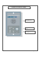
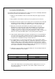
OPERATOR DISPLAY PANEL Built in Airflow sensor LED indication & Mute button LED indication and Alarm Set Potentiometer 2
1.
1.1 General Description All systems comprise of the following components :1 – Guardian 500 Alarm unit, 1 – AC power supply 1 – Inner sidewall adaptor If the Sash Alarm System option is included there will also be a sash micro switch or proximity switch. Operator Features --- the alarm has the following operator features :- Normal Airflow - Green LED (Not flashing) will be displayed if the airflow is greater than the Low air alarm point.
External Connections -- the alarm unit will have the following connection points :- External Alarm --- volt free relay input ( close contact to activate the input ) Alarm Disable Sash High Input: --- volt free relay input ( close contact to activate the input ) a. Connection point for Sash High micro switch. ( Switch contact to close and remain closed in Sash High condition ) b. Connection point for Sash High proximity switch.
1.2 Events / actions Safe airflow • Airflow above alarm level ( e.g.
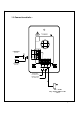
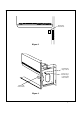
2.0 Guardian 500 Installation Procedure 1. The Fume Hood comes prepared to accept the Guardian 500 airflow alarm system. 2. First, remove the front panel by lifting it straight up and out away from the hood. 3. Next, remove the cover plate located at the top of the right corner post. 4. Install the monitor to the upper right corner post using the two screws that came with your kit. See figure 2. 5. The connection of the air monitor, adaptor and hose will follow next. a.
Guardian 500 Airflow Monitor . . Figure 2 Install Sidewall Adaptor with nut . .
2.1 Guardian 500 Calibration :Each alarm module and enclosure/fume hood is unique and needs to be individually calibrated in the field. The procedure for the adjustment is as follows: 1. Double check the installation to make sure that monitor and power supply are properly installed. 2. Allow 10 minutes for the monitor to warm up once the power has been connected. 3. Determine the low flow set point for your monitor. This is the value where the monitor will first indicate a low flow condition.
2.2 Guardian Alarm Activation :- The audio and visual alarm will activate approximately 10-30 seconds after an alarm condition is detected. To temporarily mute the audible alarm, press and release the mute button. NOTE: After an alarm condition has been detected, the red light will stay on. The audible alarm will remain muted until the airflow returns to normal levels.
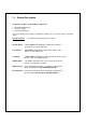
3.0 Dimensions Alarm Panel Dimensions 40.5mm (1.59 ″) 40.5mm (1.59 ″) 29mm (1.14″) R1 232 C 1 2 s 111mm (4.37 ″) 132mm (5.2 ″) 3 IDC 74mm (2.91 ″) 15V 29mm (1.14″) 81mm (3.19″) 48mm (1.89 ″) Front View 19mm (0.75 ″) Rear View 9.75mm (0.38 ″) Side View 2 x Fixing Holes 2.5mm dia for 2 x No. 6 Self tapping screws provided Panel Cutout Dimensions 3.00″ x 2.00″ 76.2mm (3.00″) 111mm (4.37″) NOT TO SCALE 50.8mm (2.
4.0 LIMITATION OF WARRANTY AND LIABILITY Seller warrants that this product, under normal use and service as described in the operator’s manual shall be free from defects in workmanship and material for a period of twelve (12) months, or the length of time specified in the operator’s manual, from the date of shipment to the customer. This limited warranty is subject to the following exclusion :a. b. c. d.