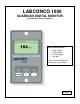
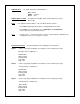
LABCONCO 1000 GUARDIAN DIGITAL MONITOR Operating and Instruction Manual Model: Guardian 1000 / 1 • • • • Digital display 3 Relay inputs 3 Relay outputs Com port Used for alarm indication and monitoring on Fume Hoods 05/03/04 1
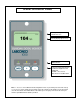
OPERATOR DISPLAY PANEL Velocity Bar Graph or Alarm Time Line Velocity display fpm or m/sec LED indicators Function and up/down buttons for Menu Configuration and Calibration. ENTER – also used as Mute button for audible alarm Note :- Access to the Calibration and Configuration menus is password protected and is factory set.
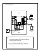
Connection details :- Sash High Proximity switch ( Optional ) 0-10V OUTPUT 1 OUTPUT RELAY R1 RS 232 Com Port - Blu s/w Blk INPUT 3 Brn + Sash High Micro - switch ( Optional ) INPUT 2 IDC 14-way Connector for remote Interface Box ( Optional ) INPUT 1 15V DC POWER SUPPLY INPUT TEL MADE IN ENGLAND www.tel-uk.
1.1 General Description All systems comprise of the following components :1 – SM6 Airflow Sensor, 1 – AFA1000 /1 Alarm unit, 1 – AC power supply If the Sash Alarm System option is included there will also be a sash micro switch or proximity switch. Operator Features --- the alarm has the following operator features :- Digital Display The digital display is a back-lit, full graphic unit with a visual display of approx 56 x 27 mm.
LED Indicators ---- the alarm unit has three LED indicators :Red -- Alarm Amber -- Caution Green -- Safe Audible Alarm sounder -- the alarm has an audible alarm sounder with local or remote Mute facility Enter --- the alarm has an Enter button -- this is multi-functional as follows :Press Enter momentarily when alarm is sounding will mute the alarm Press Enter for 5 secs will gain access to Calibration and Configuration menus ( both menus password protected ) +/- -- the alarm has + / - buttons that can
Output 1 --- volt free relay output configurable as normally closed or normally open relays. Output 2 --- volt free relay output configurable as normally closed or normally open relays. Output 3 --- volt free relay output configurable as normally closed or normally open relays.
1.2 Alarm Configuration / Calibration The alarm can be configured via a Laptop or PC using a variety of ‘set up ’ programs each designed for a particular application with a combination of inputs , outputs and push buttons. This configuration can be changed via the alarm key pad using the menu system if required or re-configured by re-connection of the laptop or PC. This allows the fume hood manufacturer to stock standard units and configure the alarms to suit the application.
1.4 Events / actions Safe airflow • • Meter reading above warning level ( e.g. > 90fpm ) Green LED on Warning airflow • • Meter reads between warning level and air fail level ( e.g.
High / Low • • • When input configured as High/Low is activated Display Icon shows High or Low High / Low relay operates ( if configured ) This function is designed for two speed fan operation or two position damper operation switched via a micro switch or proximity switch activated at a given position on the sash.
2.1 Quick Start Installation Follow the instructions below for installing and commissioning the unit. :1. Fit the alarm to the Fume Hood using the cut-out details provided with the unit --- see page 12 2. Fit the airflow sensor to the Fume Hood using the cut out and installation details provided --- see page 12 ,13 & 14 3. Connect the ‘telephone style’ airflow sensor plug-in cable to the sensor and the back of the alarm unit --- see typical connection diagram on page 15 & 16 4.
2.2 Calibration Notes :1. When using a standard Fume Hoods with Vertical Sliding sashes open the sash to the normal max safe working height for the Low Air sample. 2. For the Higher Air sample close the sash to approx 50% of the opening used for the Lower Air sample. If the Higher air sample value is too close to the Lower Air sample the alarm will detect this and ask you to repeat with a higher value. To do this close the sash a little more and repeat the sample. Avoid closing the sash below 100mm. 3.
3.0 Dimensions Alarm Panel Dimensions 40.5mm (1.59 ″) 40.5mm (1.59 ″) 29mm (1.14″) R1 s 232 1 2 111mm (4.37 ″) 132mm (5.2 ″) 3 IDC 74mm (2.91 ″) 15V TEL 29mm (1.14″) 81mm (3.19″) 48mm (1.89 ″) Front View 19mm (0.75 ″) Rear View 9.75mm (0.38 ″) Side View 2 x Fixing Holes 2.5mm dia for 2 x No. 6 Self tapping screws provided Panel Cutout Dimensions 3.00″ x 2.00″ 76.2mm (3.00″) 111mm (4.37″) NOT TO SCALE 50.8mm (2.
3.0 Dimensions 12mm (0.47″) 12mm (0.47″) 25mm (0.98″) 25mm (0.98″) 2 x Holes for self tapping fixing screw. [ 4mm (0.157″)Fixing Hole provided on SM6 sensor ] 74mm (2.91″) 20mm (0.79″) 30mm Dia (1.18″) Sensor Hole for Vent Tube 17mm 10mm (0.39″) 10mm (0.39″) 74mm (2.91″) SM6 Sensor Dimensions ( Rear view ) 12mm Dia. (0.47″) for SM1 cable 27mm (1.
4.0 SM6 Airflow Sensor Installation SM6 Airflow Sensor ( See exploded view below ) 100mm 100mm Norm al Sash working height. eg. 500mm 25mm Female adapter SM6 Sensor Open to the laboratory 25mm Tube 25mm Male bush Fume hood inner skin Fume hood outer skin It is very important to position the SM6 airflow sensor in the correct position to give long term stable reading of the face velocity. Please read the INSTALLATION NOTES below and if in doubt contact us for further advice. INSTALLATION NOTES :1.
5.0 Typical Wiring Diagram --- (Alarm only) Sash High Proximity switch ( Optional ) 0-10V OUTPUT 1 OUTPUT RELAY R1 Blu s/w RS 232 Com Port Blk INPUT 3 Brn + INPUT 2 IDC 14-way Connector for remote Interface Box ( Optional ) INPUT 1 15V DC POWER SUPPLY INPUT TEL MADE IN ENGLAND www.tel-uk.
5.1 Typical Wiring Diagram with Optional Relay Interface Unit Optional Relay Interface Unit in ABS enclosure mounted on top of Fume Hood to allow up to external cable connections to be terminated.
6.0 LIMITATION OF WARRANTY AND LIABILITY Seller warrants that this product, under normal use and service as described in the operator’s manual shall be free from defects in workmanship and material for a period of twelve (12) months, or the length of time specified in the operator’s manual, from the date of shipment to the customer. This limited warranty is subject to the following exclusion :a. b. c. d.
FILE NUMBER AFA 1000 / 1 -- ALARMS -- ( Velocity ) TYPE CUSTOMER The AFA1000 alarm has been factory set to the listed parameter settings. To change any parameter setting press and hold the enter button until the "Main Menu" screen is displayed, select "Configure" to view the parameters and use the +/- and Enter buttons to change the settings. FOR FULL INSTALLATION / CALIBRATION / CONFIGURATION DETAILS PLEASE REFER TO THE DATA BOOKLET PROVIDED.
ON INPUT 2 NOT ACTIVE Not active ACTIVE ON CLOSING CONTACT ACTIVE ON OPENING CONTACT ON INPUT 2 - FUNCTION NONE None ALARM DISABLE NIGHT SET-BACK EXTERNAL ALARM SASH HIGH HIGH/LOW ON INPUT 3 NOT ACTIVE ACTIVE ON CLOSING CONTACT ACTIVE ON CLOSING CONTACT ACTIVE ON OPENING CONTACT ON INPUT 3 - FUNCTION NONE ALARM DISABLE NIGHT SET-BACK EXTERNAL ALARM SASH HIGH SASH HIGH HIGH/LOW ON OUTPUT RELAY 1 ACTIVATION CONTACT CLOSES ON ACTIVATION ON OUTPUT RELAY 2 ACTIVATION CONTACT CLOSES ON ACTIVA
ON EXTERNAL ALARM - LED ON OFF ON ON EXTERNAL ALARM - DISPLAY ICON EXTERNAL ALARM - RELAY OFF ON OFF OFF NONE None OUTPUT RELAY 1 OUTPUT RELAY 2 OUTPUT RELAY 3 FACTORY PASSWORDS USER PASSWORD ALARM SERIAL NUMBER CONFIG 0000 CONFIG CALIBRATION 0000 CALIBRATION 4