User’s Manual FreeZone Plus™ 4.5 Liter Cascade Freeze Dry Systems Models 73820 Series 73860 Series 73870 Series To receive important product updates, complete your product registration card online at register.labconco.com Labconco Corporation 8811 Prospect Avenue Kansas City, MO 64132-2696 800-821-5525, 816-333-8811 FAX 816-363-0130 E-MAIL labconco@labconco.com HOME PAGE www.labconco.com Please read the User’s Manual before operating the equipment.
Copyright © 2008, 2009, 2012, 2013, 2014 Labconco Corporation. All rights reserved. The information contained in this manual and the accompanying products are copyrighted and all rights reserved by Labconco Corporation. Labconco Corporation reserves the right to make periodic design changes without obligation to notify any person or entity of such change. Warranty Labconco provides a warranty on all parts and factory workmanship.
TABLE OF CONTENTS CHAPTER 1: INTRODUCTION Freeze Dry Process Freeze Dry Rates Freeze Dry Capacity Samples Containing Volatile Substances Safety Symbols 1 1 2 3 4 4 CHAPTER 2: PREREQUISITES Electrical Requirements Location Requirements Vacuum Pump Requirements Chamber or Manifold Requirements 6 6 6 7 7 CHAPTER 3: GETTING STARTED Unpacking Your Freeze Dryer Freeze Dryer Components Setting Up Your Freeze Dryer Vacuum Pump Connection Electrical Connection Drying Chamber or Drying Manifold Installation Chemi
Alarms Power Failure Line Voltage Out of Range Temperature Out of Range Service Vacuum Pump Moisture in Collector 23 23 23 24 24 24 CHAPTER 5: MAINTAINING YOUR FREEZE DRYER 25 CHAPTER 6: USING THE RS232 RECEPTACLE Computer Connection for Computer Interface 27 27 CHAPTER 7: TROUBLESHOOTING Vacuum Pump Gaskets, Tubing, Connections, Sample Valves System Components & Collection Chamber Isolation Refrigeration Module Operation 31 31 32 34 36 CHAPTER 8: MODIFYING YOUR FREEZE DRYER DISPLAY Temperature and
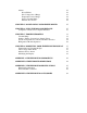
CHAPTER 1 INTRODUCTION Congratulations on your purchase of a Labconco FreeZone® Freeze Dry System, which is designed for laboratory lyophilization procedures. The refrigerant used in the refrigeration system is CFC-free so it will not endanger the environment. The unit is easy to install and maintain. Proper care and maintenance of this product will result in many years of dependable service.
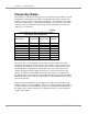
Chapter 1: Introduction Freeze Dry Rates The efficiency of the freeze drying process is dependent upon the surface area and the thickness of the sample, the collector temperature and vacuum obtained, the eutectic point and solute concentration of the sample. It is important to remember these factors when trying to obtain efficient utilization of your freeze dry system. A listing of selected materials and their approximate drying times are shown in Table 1 for your reference.
Chapter 1: Introduction In order for lyophilization to occur, ice must be removed from the frozen sample via sublimation. This is accomplished by the collector and the vacuum pump. The collector, which should be at least 15 to 20°C colder than the eutectic temperature (melting temperature) of the sample, traps vapor as ice. Since the vapor pressure at the collector is lower than that of the sample, the flow of water vapor is from the sample to the collector.
Chapter 1: Introduction If there is a problem with a particular type of sample melting when placed on the freeze dry system, dilution of the sample with more water or providing some insulation around the flask to decrease the rate of heat absorption by the sample may help.
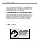
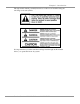
Chapter 1: Introduction Throughout this manual potentially hazardous conditions are identified using the following words and symbols. It is important that you understand the warnings listed throughout this manual before you operate the freeze dry system.
CHAPTER 2 PREREQUISITES Before you install your freeze dryer, you need to prepare your site for installation. Carefully examine the location where you intend to install your freeze dryer. You must be certain that the area is level and of solid construction. An electrical source must be located near the installation site. Carefully read this chapter to learn: the electrical supply requirements. the vacuum pump requirements.
Chapter 2: Prerequisites Refer to Appendix C: Freeze Dryer Specifications for dimensional drawings of the Freeze Dryer. The space for benchtop models must be large enough to accommodate the vacuum pump, which will be used with the freeze dryer. Vacuum Pump Requirements A vacuum pump must be provided by the user. A vacuum pump with a displacement of 86 liters per minute and 0.002 mBar ultimate pressure is adequate for most samples.
CHAPTER 3 GETTING STARTED Now that the site for your freeze dryer is properly prepared, you are ready to unpack, inspect, install and test your freeze dryer. Read this chapter to learn how to: 8 unpack and move your freeze dryer. set up your freeze dryer. connect the electrical supply source to your freeze dryer. properly exhaust your freeze dryer. safely use solvents with your freeze dryer.
Chapter 3: Getting Started Unpacking Your Freeze Dryer Carefully unpack your freeze dryer and inspect it for damage that may have occurred in transit. If your freeze dryer is damaged, notify the delivery carrier immediately and retain the entire shipment intact for inspection by the carrier. The Benchtop FreeZone Plus Cascade 4.5 Liter Freeze Dry System weighs over 125 lbs. (57 Kg). The Console FreeZone Plus Cascade 4.5 Liter Freeze Dry System weighs over 176 lbs. (80 Kg).
Chapter 3: Getting Started 7387071 4.5L Console Cascade Freeze Dryer 230 50 7382020 7382021 7382030 7382031 7382032 7382033 7382034 7382035 7382040 4.5L -105C Benchtop Freeze Dryer 4.5L -105C Benchtop Freeze Dryer 4.5L -105C Benchtop Freeze Dryer 4.5L -105C Benchtop Freeze Dryer 4.5L -105C Benchtop Freeze Dryer 4.5L -105C Benchtop Freeze Dryer 4.5L -105C Benchtop Freeze Dryer 4.5L -105C Benchtop Freeze Dryer 4.
Chapter 3: Getting Started Setting Up Your Freeze Dryer After you verify receipt of the proper components, move your freeze dryer to the location where you want to install it. Then, follow the steps listed below. Vacuum Pump Connection A vacuum pump as described in Chapter 2: Prerequisites is required to operate your freeze dry system properly. The freeze dryer is equipped with a 3/4" ID, heavy wall, vacuum hose for connecting the collector chamber to the vacuum pump.
Chapter 3: Getting Started Chemical Resistance of Freeze Dryer Components The FreeZone Freeze Dry System is designed to be chemically resistant to most compounds that are commonly used in freeze drying processes. However, by necessity, the freeze dryer is comprised of a number of different materials, some of which may be attacked and degraded by certain chemicals. The degree of degradation is dependent on the concentration and exposure duration.
Chapter 3: Getting Started The oil in the vacuum pump should be checked often. It must be changed if it is cloudy, shows particles or is discolored. The useful life of vacuum pump oil can be extended if the vacuum pump is operated for an extended period of time after a freeze dry run. This allows contaminants to be purged from the hot oil. This must be done with the inlet to the pump blocked off to prevent air from free flowing through the pump.
CHAPTER 4 USING YOUR FREEZE DRYER After your Freeze Dryer has been installed as detailed in Chapter 3: Getting Started, you are ready to begin using your Freeze Dryer. Read this chapter to learn how to: operate the controls. understand the display. connect samples. Do not use the freeze dryer in a manner not specified by the manufacturer (refer to Appendix C: Freeze Dryer Specifications).
Chapter 4: Using Your Freeze Dryer Freeze Dryer Controls The control panel for the freeze dryer is shown below with a description about its function. 1 2 5 10 7 11 9 8 6 4 12 3 1. LCD Display – Displays system operating parameters, set-up parameters and alarm messages. 2. Menu Switch – This switch is used to change the display from operating system parameters to set-up parameters. 3. Select Switch – Used to select set-up parameters. 4.
Chapter 4: Using Your Freeze Dryer 11. Collector Temperature Graph Display – This display indicates the temperature of the collector. The highest LED indicates the collector temperature is warmer than 10°C. The indicators will sequence down when the temperature reaches 10, 0, -10, -20, -30, -40°C (-10, -20, -30, -40, -50, -60 for Models 73820xx). When the collector temperature is –40°C (-60°C for Models 73820xx) or lower the green indicator will light. 12.
Chapter 4: Using Your Freeze Dryer Operating the Freeze Dryer Set-Up The freeze dryer may be configured to automatically start the vacuum pump when the collector temperature reaches –40°C. The display units for vacuum may be selected to be mBar, Pascal (Pa) or Torr and the temperature may be displayed as °F or °C. The run time of the refrigeration system and the vacuum pump may be monitored. To configure your freeze dryer, turn the main power switch ON and press MENU.
Chapter 4: Using Your Freeze Dryer Press SELECT until the desired units are flashing. Press MENU. The display shows: REFRIG TOTAL HOUR: XXXX SERVICE HOUR: XXXX To reset the SERVICE HOUR to 0 press SELECT. This allows you to keep track of the time the refrigeration system operated since it was serviced. The display shows the refrigeration system hours.
Chapter 4: Using Your Freeze Dryer To change the rate press SELECT until the desired time interval is shown. The time between data transmissions may be set to occur at 10, 30, 60, 300 or 600 second intervals. Press MENU to return to display operating parameters or after a short delay, the display will automatically switch to show operating parameters. Automatic Start-Up To run the Auto Mode, press the panel switch labeled REFRIGERATION AUTO.
Chapter 4: Using Your Freeze Dryer Setting the Operating Vacuum Level The vacuum level may be set by the user to optimize the freeze dry process. Normally, the sublimation rate will increase if there is less vacuum (a higher pressure) in the freeze dryer. A good starting place is to set the vacuum so its level is equivalent to about 10°C colder than the eutectic or collapse temperature of the sample. Adjustments to the vacuum level must be made for various freeze drying conditions.
Chapter 4: Using Your Freeze Dryer Adding Sample The following procedure should be followed when using sample valves in the freeze dry process: 1. Connect a pre-frozen sample to a sample valve on the drying chamber or manifold using an adapter. Turn the plastic valve knob to the “VACUUM” position to open the valve, which connects the attached sample to system vacuum. The bevel on the knob should be positioned toward the sample port to apply vacuum to the sample.
Chapter 4: Using Your Freeze Dryer 5. Ampules may be flame sealed while connected to a valve by using a sealing torch. Care must be taken not to burn the valve. An insulation material placed between the valve and the torch is recommended. Shut Down At the end of a run or when a sufficient amount of condensate accumulates on the collector coil to obstruct the flow of vapor to the collector chamber, the Freeze Dryer should be defrosted.
Chapter 4: Using Your Freeze Dryer Alarms A number of unusual events may occur during a lyophilization procedure that can adversely effect the operation of the freeze dryer. If an event occurs, the alarm indicator flashes and the beeper sounds. The beeper automatically mutes itself after one minute. The specific alarm can be identified by pressing MENU. Pressing MENU multiple times displays multiple alarms if they have occurred.
Chapter 4: Using Your Freeze Dryer Temperature Out of Range An alarm activates if the collector temperature rises above –40°C (-60°C for Models 73820xx). If this occurs, the display shows: COLLECTOR TEMPERATURE HOLD SELECT TO CLEAR IT Press and hold SELECT for five seconds until the error message is cleared from the display. Service Vacuum Pump The vacuum pump normally plugs into the vacuum pump electrical receptacle on the back of the freeze dryer.
CHAPTER 5 MAINTAINING YOUR FREEZE DRYER Under normal operation, the freeze dryer requires little maintenance. The following maintenance schedule is recommended: As needed: 1. Clean up all spills; remove liquids from the chamber. 2. Clean lid and gasket using soft cloth, sponge or chamois and a mild, nonabrasive soap or detergent. 3. Check oil level of the vacuum pump. It should be between MIN and MAX. If the oil level is less than an inch (25.4 mm) above MIN, add oil to proper level. 4.
Chapter 5: Maintaining Your Freeze Dryer Monthly: 1. The rubber components on the freeze dryer may eventually deteriorate and require replacement. The effective life of rubber parts depends upon both their usage and the surrounding environment. Check all rubber hoses and gaskets and replace any that show signs of hardening, permanent set or deterioration. 2. Using a soft cloth, sponge or chamois and a mild, non-abrasive soap or detergent, clean the acrylic chamber lid. 3.
CHAPTER 6 USING THE RS232 RECEPTACLE The operation of the freeze dryer can be monitored using a computer when it is connected to the RS232 receptacle on the rear panel. The computer cannot control the operation of the freeze dryer. The monitored parameters are the collector temperature in °C and vacuum in microbars. Computer Connection for Computer Interface Check your computer to see which type of serial port is provided, then use a connecting cable below: 1.
Chapter 6: Using the RS232 Receptacle The time between data transmissions may be varied by the user to occur at 10, 30, 60, 300 or 600 second intervals. Press the MENU button until the RS232 screen appears on the display. RS-232 TRANSMISSION RATE 10 SECONDS Press select until the desired time interval is shown.
Chapter 6: Using the RS232 Receptacle 3. The “Connection Description” dialogue box opens. Type in a user defined name and select an icon for the new connection. Press “OK.” 4. The “Connect To” dialogue box opens. Using the down arrow selection button, select the communication port to which the cable has been connected. Press “OK.
Chapter 6: Using the RS232 Receptacle 5. The “Com X Properties” dialogue box opens. Enter the appropriate data properties and press “OK.” 6. When the freeze dryer main power switch is on, the data is transmitted and updated at the time intervals selected by the user.
CHAPTER 7 TROUBLESHOOTING Refer to the following if your freeze dryer fails to operate properly. If the suggested corrective actions do not solve your problem, contact Labconco for additional assistance. FreeZone Freeze Dry Systems that are clean, dry and without samples attached should reach a vacuum of 0.133 mBar within 10 minutes and should achieve an ultimate vacuum of 0.040 mBar within 18 hours when the refrigeration is operating.
Chapter 7: Troubleshooting If vacuum problems continue, consider obtaining a second vacuum gauge capable of reading a vacuum of 0.010 mBar. It is often useful in determining if the vacuum pump is operating properly and the vacuum sensor reading is accurate. 4. Isolate the pump by disconnecting the vacuum hose from the freeze dryer. Deadhead the pump by inserting the vacuum sensor from a secondary vacuum gauge into the end of the vacuum hose and observe the vacuum reading obtained.
Chapter 7: Troubleshooting The illustrations below show how the sample valve installs on a chamber and a manifold.
Chapter 7: Troubleshooting III. System Components and Collection Chamber Isolation This test determines if the source of a leak is in the drying chamber. 1. Remove the drying chamber or manifold. 2. Leave the gasket on and turn a large freeze dry flask upside down to cover the connection port. 3. Start the freeze dryer and observe the vacuum indication.
Chapter 7: Troubleshooting The following test determines if a vacuum leak is in the collection chamber. 1. Insert a rubber stopper in the small hole in the rear of the collector chamber and another in the drain port in the bottom. 2. Start the freeze dryer and observe the vacuum indication. If the vacuum is good, the problem is in the collection chamber. If it is bad, the problem is in the plumbing connections from the collection chamber to the vacuum pump. 3.
Chapter 7: Troubleshooting Refrigeration Module Operation Under a no-load condition, FreeZone Plus Cascade Freeze Dry Systems should achieve a collector temperature of –84°C (models 73860xx and 73870xx) or -105°C (models 73820xx) or lower when the vacuum pump is operating. If the collector temperature does not reach the design temperature within 30 minutes, then the refrigeration module is not functioning properly.
CHAPTER 8 MODIFYING YOUR FREEZE DRYER DISPLAY Your freeze dryer has been carefully calibrated and tested before shipping, however under certain circumstances it may be necessary to adjust the calibration of the temperature and/or vacuum display or to modify alarm points. Adjustments may be necessary if the freeze dryer requires service or if it is operating on a line voltage outside the voltage range at which the alarm was preset.
Chapter 8: Modifying Your Freeze Dryer Display High line limit may be raised in 5 increments of approximately 4 to 5V increments for 230V models or disabled. Moisture Sensor Alarm The moisture sensor alarm may be disabled. It is shipped enabled as the factory default setting.
Chapter 8: Modifying Your Freeze Dryer Display Press MENU and if the drying chamber has been installed, the display shows: SDC TEMP. OFFSET: OC Press SELECT until the appropriate offset is shown. Each number represents 1°C. Press MENU and the display shows: VACUUM OFFSET: O uBar Press SELECT until the appropriate offset is shown. Each number represents 0.001mBar. Press MENU and the display shows: LOW LINE OFFSET: 0 Press SELECT until the appropriate offset is shown.
Chapter 8: Modifying Your Freeze Dryer Display Press MENU and the display shows: DRYING CHAMBER: NOT INSTALLED Press and hold SELECT to change the status. Press MENU and the display shows: PURGE VALVE: NOT INSTALLED Press and hold SELECT to change the status. Press MENU and the display shows: DEFROST HEATER: NOT INSTALLED Press and hold SELECT to change the status. Press MENU and the display shows: MOISTURE SENSOR: INSTALLED Press and hold SELECT if you want to disable the moisture sensor.
Chapter 8: Modifying Your Freeze Dryer Display The routine repeats by pressing MENU or wait approximately 10 seconds for the display to default to the main freeze dry information display information. In order to store offsets in memory, you Must Press and Hold MENU until display shows, PASSWORD: Wait approximately 10 seconds and the display defaults to the main freeze dry display information. This can be done anytime throughout the Modifying the Display routine.
APPENDIX A FREEZE DRYER COMPONENTS The following is a list of components that are available for your freeze dryer. The parts shown are the most common replacement parts. If other parts are required, contact Product Service. Item 1 2 3 4 5 6 7 8 9 10 11 12 13 14 15 16 17 18 19 Models 73860xx, 73870xx Part No.
Appendix A: Freeze Dryer Components Models 73860xx and 73870xx Product Service 816-333-8811 or 1-800-522-7658 43
APPENDIX B FREEZE DRYER DIMENSIONS Model 73860xx 44 Product Service 816-333-8811 or 1-800-522-7658
Appendix B: Freeze Dryer Dimensions Model 73870xx Product Service 816-333-8811 or 1-800-522-7658 45
Appendix B: Freeze Dryer Dimensions Model 73820xx 46 Product Service 816-333-8811 or 1-800-522-7658
APPENDIX C FREEZE DRYER SPECIFICATIONS This Appendix contains technical information about the freeze dryer including electrical specifications, environmental operating conditions and wiring diagrams.
Appendix C: Freeze Dryer Specifications Catalog # 7382020 7382021 7382030 7382031 7382032 7382033 7382034 7382035 7382040 7382041 Voltage Nominal Operating Range 115V 115V 230V 230V 230V 230V 230V 230V 230V 230V 103-127 103-127 198-254 198-254 198-254 198-254 198-254 198-254 187-254 187-254 Frequency Phase 60 60 50 50 50 50 50 50 60 60 1 1 1 1 1 1 1 1 1 1 Amperage Nominal Max. with w/o Vacuum Vacuum Pump Pump 11.5 16 11.5 16 6.3 10 6.3 10 6.3 10 6.3 10 6.3 10 6.3 10 6.3 10 6.
APPENDIX D FREEZE DRYER ACCESSORIES The following accessories are available for the freeze dryer. PART # 1472100 DESCRIPTION Vacuum Pump Two stage direct drive pump, 117 liters/minute. 115 VAC, 50/60 Hz, single phase, 4.6 amps. Includes Pump Exhaust Filter 1473400. (Cat. # 1473400) 7739402 Vacuum Pump Two stage direct drive pump, 117 liters/minute. 230 VAC, 50/60 Hz, single phase, 2.4 amps. Includes Pump Exhaust Filter 1473400. (Cat.
Appendix C: Freeze Dryer Specifications PART # 1472200 DESCRIPTION Pump Inlet Filter Disposable filter that prevents oil back streaming and protects vacuum pump from submicron particles. Fits Vacuum Pumps 1472100 and 7739402. 1473400 Pump Exhaust Filter Disposable filter that removes visible oil mist and odor from vacuum pump exhaust. Fits Vacuum Pumps 1472100 and 7739402. 1473200 Replacement Element, Oil Mist, Pump Exhaust Filter Fits Pump Exhaust Filter 1473400.
Appendix C: Freeze Dryer Specifications PART # 7772600 DESCRIPTION Replacement Activated Carbon Media for Carbon Solvent Trap 7538000 Secondary Vacuum Cold Trap Provides additional protection for the vacuum pump when processing low eutectic samples. 9 ¾" high x 7 7/8" diameter, 304 stainless steel with ¾" vacuum connections. For use with dry ice and solvent. Cools to approximately –75°C. 7509200 Product Heater, 115V For use in chamber 7522800. Provides 3 heated shelves operating at 43°C (110°F).
Appendix C: Freeze Dryer Specifications Serum Bottles and Vials Threaded Vials Stoppers and threaded vials with Screw Caps are supplied in packages of 200. Perfect for long term storage of freeze dried samples. Labconco Serum Bottles and Treaded Vials are specifically designed for lyophilization applications. Their uniform thin wall construction ensures even freezing and drying. Bottles and vials are ideal containers for use in the FreeZone Stoppering Tray Dryer.
Appendix C: Freeze Dryer Specifications Fast-Freeze Flasks Fast-Freeze Flasks are specially designed to be easier to handle, faster to load and more convenient to use than other freeze dry glassware now in your laboratory. Compatible with all major brands of laboratory freeze dry equipment, Fast-Freeze Flasks eliminate the risk of contamination from vacuum grease, reduce spillage of valuable samples and require no washers, gaskets or retainers.
Appendix C: Freeze Dryer Specifications Lyph-Lock Flasks Lyph-Lock Flasks simplify your Lyophilization procedures because they have only three pieces per flask – a high strength borosilicate glass top and bottom with a silicone rubber ring seal. The unique wide-mouth design helps you load samples easily and lyophilize efficiently. How to select Lyph-Lock Flasks for your Freeze Dry System Select Lyph-Lock Flasks fast- based on your sample sizes.
Appendix C: Freeze Dryer Specifications Ampules Oxygen/Natural Gas Sealing Torch 7578500 Torch specifically designed for flame sealing freeze dry ampules. Seals all types of heat-resistant glass. Connects to natural gas, butane or propane and oxygen with ¼" ID hose connectors. Shipping weight 3 lbs. (1.4 kg). Labconco Ampules are fabricated of highest quality borosilicate glass for strength and durability.