User’s Manual FreeZone® Clear Stoppering Chambers Models 7868020 7868030 To receive important product updates, complete your product registration card online at register.labconco.com Labconco Corporation 8811 Prospect Avenue Kansas City, MO 64132-2696 800-821-5525, 816-333-8811 FAX 816-363-0130 E-MAIL labconco@labconco.com HOME PAGE www.labconco.com Please read the User’s Manual before operating the equipment.
Copyright © 2004, 2007, 2013 Labconco Corporation. All rights reserved. The information contained in this manual and the accompanying products are copyrighted and all rights reserved by Labconco Corporation. Labconco Corporation reserves the right to make periodic design changes without obligation to notify any person or entity of such change. Warranty Labconco provides a warranty on all parts and factory workmanship.
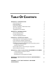
TABLE OF CONTENTS CHAPTER 1: INTRODUCTION Freeze Dry Process Freeze Dry Rates Freeze Dry Capacity Samples Containing Volatile Substances About This Manual Typographical Conventions 1 1 2 3 4 4 6 CHAPTER 2: PREREQUISITES Electrical Requirements Location Requirements Vacuum Pump Requirements 7 7 8 8 CHAPTER 3: GETTING STARTED Unpacking Your Clear Stoppering Chamber Clear Stoppering Chamber Components Setting Up Your Clear Stoppering Chamber Installing the Stoppering Chamber on the Freeze Dry System Ventin
APPENDIX B: CLEAR STOPPERING CHAMBER DIMENSIONS 25 APPENDIX C: CLEAR STOPPERING CHAMBER SPECIFICATIONS Electrical Specifications Environmental Conditions 26 26 26 APPENDIX D: CLEAR STOPPERING CHAMBER ACCESSORIES 27 DECLARATION OF CONFORMITY 28
CHAPTER 1 INTRODUCTION Congratulations on your purchase of a Labconco FreeZone® Clear Stoppering Chamber, which is designed for laboratory lyophilization procedures. The unit is easy to install and maintain. Proper care and maintenance of this product will result in many years of dependable service. Freeze Dry Process Freeze drying is an important process in sample preparation and for the preservation and storage of biologicals, pharmaceuticals and foods.
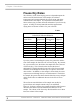
Chapter 1: Introduction Freeze Dry Rates The efficiency of the freeze drying process is dependent upon the surface area and the thickness of the sample, the collector temperature and vacuum obtained, the eutectic point and solute concentration of the sample. It is important to remember these factors when trying to obtain efficient utilization of your freeze dry system. A listing of selected materials and their approximate drying times are shown in Table 1 for your reference.
Chapter 1: Introduction In order for lyophilization to occur, ice must be removed from the frozen sample via sublimation. This is accomplished by the collector and the vacuum pump. The collector, which should be at least 15 to 20°C colder than the eutectic temperature (melting temperature) of the sample, traps vapor as ice. Since the vapor pressure at the collector is lower than that of the sample, the flow of water vapor is from the sample to the collector.
Chapter 1: Introduction If there is a problem with a particular type of sample melting when placed on the freeze dry system, dilution of the sample with more water or providing some insulation around the flask to decrease the rate of heat absorption by the sample may help.
Chapter 1: Introduction Chapter 4: Using Your Clear Stoppering Chamber discusses the basic operation of your Clear Stoppering Chamber. Information on how to load samples and run the Clear Stoppering Chamber is included. Chapter 5: Maintaining Your Clear Stoppering Chamber explains how to perform routine maintenance on your Clear Stoppering Chamber. Appendix A: Clear Stoppering Chamber Components contains labeled diagrams of the components of the Clear Stoppering Chamber.
Chapter 1: Introduction Typographical Conventions Recognizing the following typographical conventions will help you understand and use this manual: • • • • ! ) 6 • Book, chapter, and section titles are shown in italic type (e.g., Chapter 3: Getting Started). Steps required to perform a task are presented in a numbered format. Comments located in the margins provide suggestions, reminders, and references.
CHAPTER 2 PREREQUISITES Before you install your Clear Stoppering Chamber, you need to prepare your site for installation. The Clear Stoppering Chamber will mount on top of a FreeZone 6, 12 or 18 liter Freeze Dry System. This could be either a benchtop or console model. Carefully examine the location where you intend to install your Clear Stoppering Chamber. You must be certain that the area is level and of solid construction. An electrical source must be located near the installation site.
Chapter 2: Prerequisites Location Requirements The Freeze Dryer should be located in an area that provides an unobstructed flow of air around the cabinet. This air cools the refrigeration system. A minimum of 3" must be allowed between the rear and both sides of the Freeze Dryer and adjacent wall surfaces. Restriction of airflow during operation could adversely affect performance. Refer to Appendix B: Clear Stoppering Chamber Dimensions for dimensional drawings of the Clear Stoppering Chamber.
CHAPTER 3 GETTING STARTED Now that the site for your Clear Stoppering Chamber is properly prepared, you are ready to unpack, inspect, install and test your Clear Stoppering Chamber. Read this chapter to learn how to: • • • • Unpack and move your Clear Stoppering Chamber. Set up your Clear Stoppering Chamber. Connect the electrical supply source to your Clear Stoppering Chamber. Safely use solvents with your Clear Stoppering Chamber.
Chapter 3: Getting Started ) IF YOUR CLEAR STOPPERING CHAMBER WAS DAMAGED IN TRANSIT, YOU MUST FILE A CLAIM DIRECTLY WITH THE FREIGHT CARRIER. LABCONCO CORPORATION AND ITS DEALERS ARE NOT RESPONSIBLE FOR SHIPPING DAMAGE. ) DO NOT DISCARD THE CARTON OR PACKING MATERIAL FOR YOUR CLEAR STOPPERING CHAMBER UNTIL YOU HAVE CHECKED ALL OF THE COMPONENTS AND INSTALLED AND TESTED THE CLEAR STOPPERING CHAMBER.
Chapter 3: Getting Started Setting Up Your Clear Stoppering Chamber After you verify receipt of the proper components, move your Clear Stoppering Chamber to the location where you want to install it. Then, follow the steps listed below. Installing the Clear Stoppering Chamber on the Freeze Dry System 1. Place the rubber gasket over the 3” port on the top of the Freeze Dry System. 2. Position the Shelf Assembly over the 3” port. Rotate the Shelf assembly so it clears the lid over the collector. 3.
Chapter 3: Getting Started 12 Product Service: Domestic 1-800-522-7658, International 816-333-8811
Chapter 3: Getting Started The Clear Stoppering Chamber is now installed and must be tested to make certain the system is free of leaks. To test, turn on the Freeze Dry System refrigeration and allow the temperature to reach –40° or lower. Make sure the Vacuum Release control is in the “CLOSED” position. Start the vacuum pump and monitor the vacuum gauge. The vacuum on the Freeze Dry System should reach 0.133 mBar within 30 minutes and should achieve an ultimate vacuum of 0.
Chapter 3: Getting Started Chemical Resistance of Freeze Dryer Components The FreeZone Freeze Dry System and Clear Stoppering Chamber are designed to be chemically resistant to most compounds that are commonly used in freeze drying processes. However, by necessity, the Freeze Dryer is comprised of a number of different materials, some of which may be attacked and degraded by certain chemicals. The degree of degradation is dependent on the concentration and exposure duration.
Chapter 3: Getting Started • • Most common compounds used in freeze drying processes, if allowed to enter the vacuum pump, will degrade the oil and cause damage to the vacuum pump. Sugars and proteins typically will have minimal negative effect on any of the materials of construction. When using compounds in the Freeze Dryer that are hostile to the materials of construction, it is imperative the equipment is thoroughly cleaned after use.
Chapter 3: Getting Started ! Solvent Safety Precautions Solvents used in the Clear Stoppering Chamber may be flammable or hazardous to your health. Use extreme caution and keep sources of ignition away from the solvents. When using flammable or hazardous solvents, the vacuum pump must be vented to a fume hood. Hazardous materials such as strong acids or bases, radioactive substances and volatile organics must be handled carefully and promptly cleaned up if spilled.
CHAPTER 4 USING YOUR CLEAR STOPPERING CHAMBER After your Clear Stoppering Chamber has been installed as detailed in Chapter 3: Getting Started, you are ready to begin using your Clear Stoppering Chamber. Read this chapter to learn how to: • • Operate the controls. Add samples. ! Do not use the Clear Stoppering Chamber in a manner not specified by the manufacturer (refer to Appendix C: Clear Stoppering Chamber Specifications).
Chapter 4: Using Your Clear Stoppering Chamber Clear Stoppering Chamber Controls The control panel for the Clear Stoppering Chamber is shown below with a description about its function. 1. Heat Level Switch – Varies the duty cycle of the electrical power supplied to the shelves. 2. Indicator Light – Illuminates when the heat level switch is in any position other than “O”. 3. Heat Range Switch – Changes the voltage supplies to the shelves.
Chapter 4: Using Your Clear Stoppering Chamber Operation Checklist The following checklist should be followed prior to each use of your Clear Stoppering Chamber. 1. Wipe the interior of the chamber with a soft cloth or paper towel to remove any accumulated moisture. 2. Wipe the upper and lower gasket surfaces with a soft, lintfree cloth or paper towel to remove any dirt or contaminants that could cause a vacuum leak. Vacuum grease is not required on the gaskets to obtain a proper vacuum seal. 3.
Chapter 4: Using Your Clear Stoppering Chamber Setting the Shelf Temperature A specific temperature cannot be selected and set. The voltage and duty cycle of the heater is determined by the Heat Range Switch and Heat Level Switch. When the Heat Range Switch is positioned to HIGH, the voltage to the heaters is twice as high as when the switch is in the LOW position. The Heat Level Switch varies the heater on duty cycle from about 20% when the dial is set at the 1 position to 100% when the dial is set at 9.
CHAPTER 5 MAINTAINING YOUR CLEAR STOPPERING CHAMBER Under normal operation, the Clear Stoppering Chamber requires little maintenance. The following maintenance schedule is recommended: As needed: 1. The user has the responsibility for carrying out appropriate decontamination if hazardous material is spilled on or inside the equipment. This may be done by wiping the contaminated surfaces with a soft cloth dampened with alcohol. Alcohol may craze the acrylic parts.
Chapter 5: Maintaining Your Clear Stoppering Chamber Monthly: 1. The rubber components on the Clear Stoppering Chamber may eventually deteriorate and require replacement. The effective life of rubber parts depends upon both their usage and the surrounding environment. Check all rubber hoses and gaskets and replace any that show signs of hardening, permanent set or deterioration. 2. Using a soft cloth, sponge or chamois and a mild, non-abrasive soap or detergent, clean the acrylic chamber. 3.
APPENDIX A CLEAR STOPPERING CHAMBER COMPONENTS The following pages list components that are available for your Clear Stoppering Chamber. The parts shown are the most common replacement parts. If other parts are required, contact Product Service. Replacements Parts Item Qty Part No.
Appendix A: Clear Stoppering Chamber Components 24 Product Service: Domestic 1-800-522-7658, International 816-333-8811
APPENDIX B CLEAR STOPPERING CHAMBER DIMENSIONS Product Service Domestic 1-800-522-7658, International 816-333-8811 25
APPENDIX C CLEAR STOPPERING CHAMBER SPECIFICATIONS This Appendix contains technical information about the Clear Stoppering Chamber including electrical specifications and environmental operating. Electrical Specifications • Nominal amperage – Model: 7868020: 1A • Nominal amperage – Model: 7868030: 0.5A • Frequency: All Models 50/60 Hz • Phase: Single Environmental Conditions • Indoor use only. 26 • Maximum altitude: 6562 feet (2000 meters). • Ambient temperature range: 41° to 104°F (5° to 40°C).
APPENDIX D CLEAR STOPPERING CHAMBER ACCESSORIES The following serum bottles and vials are available for the Clear Stoppering Chamber.
28 Product Service Domestic 1-800-522-7658, International 816-333-8811