User’s Manual CentriVap® Centrifugal Concentrators and Cold Traps Models 78100 Series 78110 Series 74600 Series 73850 Series 79820 Series 79830 Series 79840 Series 74750 Series To receive important product updates, complete your product registration card online at register.labconco.com Labconco Corporation 8811 Prospect Avenue Kansas City, MO 64132-2696 800-821-5525, 816-333-8811 FAX 816-363-0130 E-MAIL labconco@labconco.com HOME PAGE www.labconco.
Copyright © 2005, 2007, 2010, 2013 Labconco Corporation. All rights reserved. The information contained in this manual and the accompanying products are copyrighted and all rights reserved by Labconco Corporation. Labconco Corporation reserves the right to make periodic design changes without obligation to notify any person or entity of such change. Warranty Labconco provides a warranty on all parts and factory workmanship.
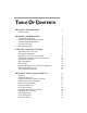
TABLE OF CONTENTS CHAPTER 1: INTRODUCTION Safety Symbols 1 2 CHAPTER 2: PREREQUISITES Electrical Requirements Location and Exhaust Requirements Vacuum Pump Requirements Vacuum Line Traps Space Requirements 3 4 4 5 5 5 CHAPTER 3: GETTING STARTED Unpacking Your CentriVap CentriVap Components Emergency Access Into the Chamber Component Orientation & Hose Connections Electrical Connection Rotor Installation Ground Wire Chemical Resistance of CentriVap Components Chemical Resistance Chart Solvent Safety Prec
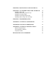
CHAPTER 5: MAINTAINING YOUR CENTRIVAP 22 CHAPTER 6: ACCESSORIES FOR YOUR CENTRIVAP Installing a Glass Lid Installing a Secondary Chemical Trap Installing a Vacuum Gauge Installing a CentriZap Strobe Light Installing a Glass Trap in the Cold Trap 24 27 27 28 29 30 CHAPTER 7: TROUBLESHOOTING 31 APPENDIX A: CENTRIVAP COMPONENTS 34 APPENDIX B: CENTRIVAP DIMENSIONS 42 APPENDIX C: CENTRIVAP SPECIFICATIONS Electrical Specifications Environmental Conditions Evaporation Rates 46 46 47 48 DECLARATION OF C
Chapter 1: Introduction Congratulations on your purchase of a Labconco CentriVap Concentrator System. Models are available for operation on 115V or 230V. The CentriVap Concentrator, when combined with the CentriVap Cold Trap, uses centrifugal force with heat and vacuum to rapidly evaporate and condense solvents from biological and analytical samples. Centrifugation eliminates bumping and foaming as vacuum is applied and also concentrates the solute in the bottom of the vial.
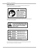
Chapter 1: Introduction Safety Symbols Your CentriVap Concentrator was designed with safety in mind, however conditions may exist that could be hazardous. Throughout this manual potentially hazardous conditions are identified using the following words and symbols. It is important that you understand the warnings listed throughout this manual before you operate the CentriVap Concentrator.
Chapter 2: Prerequisites Before you install your CentriVap, you need to prepare your site for installation. You must be certain that the area is level and of solid construction. In addition, a means to exhaust the vacuum pump must be provided. An electrical source must be located near the installation site. Carefully read this chapter to learn: • The electrical supply requirements. • The exhaust requirements. • The vacuum pump requirements.
Chapter 2: Prerequisites Electrical Requirements The CentriVap Concentrator requires a dedicated grounded electrical outlet. This outlet requires a 15 Amp circuit breaker or fuse for models rated at 115V (60 Hz). An 8 Amp circuit breaker or fuse is required for models rated at 230V (50/60 Hz). If the power cord supplied with the Concentrator does not match the available receptacle, replace it with an approved power cord of the suitable style.
Vacuum Pump Requirements A vacuum pump must be provided by the user. A vacuum pump with a free air flow rate of 82 liters per minute and < 2 mBar ultimate pressure is adequate for aqueous samples. More volatile samples can be satisfactorily processed using a diaphragm pump with a free airflow of 42 liters per minute and 200 mBar vacuum. The inlet fitting on the vacuum pump must be suitable for 0.50 ID hose. Vacuum pumps used with 115V models should be equipped with a 115V, 15 Amp NEMA 5-15P plug.
Chapter 3: Getting Started Now that the site for your CentriVap is properly prepared, you are ready to unpack, inspect, install, and test your CentriVap. Read this chapter to learn how to: • Unpack and move your CentriVap. • Set up your CentriVap. • Connect the electrical supply source to your CentriVap. • Properly exhaust your CentriVap. • Safely use solvents with your CentriVap. CAUTION: The CentriVap Concentrator weighs over 42 lbs. (19 Kg).
Chapter 3: Getting Started Unpacking Your CentriVap Carefully unpack your CentriVap and inspect it for damage that may have occurred in transit. If your CentriVap is damaged, notify the delivery carrier immediately and retain the entire shipment intact for inspection by the carrier. The United States Interstate Commerce Commission rules require that claims be filed with the delivery carrier within fifteen (15) days of delivery.
Chapter 3: Getting Started Concentrators 1334500 1336100 1332600 1332700 1338000 7828606 1488800 7397601 7396206 7539800 Voltage (V) Frequency (Hz) Connector: IEC C13 Plug: NEMA 5-15 Connector: IEC C13 Plug: CEE 7/7 Connector: IEC C13 Plug: BS 1363 Connector: IEC C13 Plug: CH1-10P Connector: IEC C13 Plug: NEMA 6-15 Tubing clamps (2) Coupling Insert (Std.
System Type Aqueous Aqueous Aqueous Aqueous Aqueous Acid Acid Acid Acid Acid Solvent Solvent Solvent Solvent Solvent Gel Drying Gel Drying Gel Drying Catalog # 7982010 7982011 7982012 7982035 7982037 7983013 7983014 7983015 7983035 7983037 7984010 7984011 7984012 7984035 7984037 7475010 7475011 7475012 Voltage (V) 115 230 230 230 230 115 230 230 230 230 115 230 230 230 230 115 230 230 Frequency (Hz) 60 50 60 50 50 60 50 60 50 50 60 50 60 50 50 60 50 60 7810010 Product Service 1-800-522-7658 X X 7
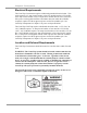
Chapter 3: Getting Started If you do not receive one or more of the components listed for your CentriVap, contact Labconco Corporation immediately for further instructions. Emergency Access into the Chamber The CentriVap is designed to prevent access to the chamber in the event of a power disruption.
Chapter 3: Getting Started After positioning the components, it is necessary to join the system together using the hoses provided. Attach one hose to the tube that extends out the back of the Concentrator. Attach the other end of this hose to one of the barb fittings on the Cold Trap Cover Assembly. Secure the hoses with the clamps supplied. Attach another hose to the remaining barb fitting on the Cold Trap Cover and clamp securely.
Chapter 3: Getting Started Electrical Connection Plug the power cord into the receptacle on the back of the CentriVap Concentrator and plug the other end into a suitable power receptacle. Plug the power cord into the receptacle on the back of the CentriVap Cold Trap and plug the other end into a suitable power receptacle. Plug the power cord from the vacuum pump into the receptacle on the back of the Concentrator. If the vacuum pump has an off/on switch, turn the switch ON.
Chapter 3: Getting Started Rotor Rotor Shaft & Cold Trap Bearings Anodized Aluminum Stainless Steel High Carbon Steel C D C C D D D D D C D D D D D D D C D D D D D D D D D C D D C D C D C Water Toluene Methylene Chloride D D D D D D C D D D D D D D D C D D D D D D C-Moderate Degradation - Questionable use D-Severe Degradation - Infrequent use recommended - immediate thorough neutralizing and cleaning is required.
Chapter 3: Getting Started • If the compounds used attack acrylic, consider using the optional glass chamber lid. See Chapter 6: Accessories for Your CentriVap. • If the stainless steel cold trap chamber is attacked by the compounds in use consider using the optional Glass Trap insert. See Chapter 6: Accessories for Your CentriVap. • When using a rotary vane vacuum pump the oil in the pump should be checked often. It must be changed if it is cloudy, shows particles or is discolored.
Chapter 3: Getting Started CAUTION: Solvents used in the CentriVap may be flammable or hazardous. Use extreme caution and keep sources of ignition away from the solvents. When using flammable or hazardous solvents, both the CentriVap and the vacuum pump should be operated inside a fume hood. If a sample is spilled in the chamber it must immediately be cleaned up.
Chapter 4: Using Your CentriVap After your CentriVap has been installed as detailed in Chapter 3: Getting Started, you are ready to begin using your CentriVap. Read this chapter to learn how to: • Set operating parameters. • Operate the controls. • Properly select and position glassware inside your CentriVap. • Understand the display. • Interrupt a cycle after it has begun. Note: See Appendix C: CentriVap Specifications for electrical requirements.
Chapter 4: Using Your CentriVap Loading Glassware into the CentriVap Smooth operation of the CentriVap is dependent upon proper balance of the machine. Therefore, if less than a full load of samples is run, it is important to load samples into the CentriVap in a fairly symmetrical manner distributing the weight of the samples evenly in the sample rotor. Temperature Setting Guidelines The evaporation rate achieved by the CentriVap is dependent upon a variety of factors.
Chapter 4: Using Your CentriVap CentriVap Controls The control panel for the CentriVap is shown below with a description about its function. 1. Display – The liquid crystal display (LCD) shows set point parameters and actual measured conditions. 2. Program Buttons – Used to initiate the start of a run with the use of just one button. 3. Run/Stop Button – Press this to start or stop a run. 4. Preheat Button – Used to turn on the heater to preheat the chamber prior to loading samples. 5.
Chapter 4: Using Your CentriVap Select existing program: Operating parameters can be stored in memory so protocols can be repeated. Nine programs can be stored. To select a program, press the set point “SELECT” button until arrows point to the program number indicating that this set point can be run or altered. To change the program number, press the increase or decrease button until the desired program number is displayed.
Chapter 4: Using Your CentriVap Operating the CentriVap CAUTION: To avoid personnel injury; Do not operate the CentriVap if the lid is scratched or nicked, or shows signs of damage. A damaged lid could fail under vacuum. While the CentriVap Concentrator is operating, do not lean on the lid, do not stand near it longer than necessary and do not place hazardous materials within 12 inches. 1. Press the Cold Trap “ON” switch. The top amber indicator will illuminate.
Chapter 4: Using Your CentriVap 10. Set point parameters can be altered at any time during a run by first selecting the parameter using the set point “SELECT” button and then pressing the “INCREASE” or “DECREASE” switch. 11. If the time set point is used, at the end of the set time an alarm sounds. All functions cease. 12. Press “STOP” to terminate operation if the CentriVap has not already stopped itself. 13.
Chapter 5: Maintaining Your CentriVap Under normal operation, the CentriVap requires little maintenance. The following maintenance schedule is recommended. Before servicing the CentriVap, disconnect electrical power. Special precautions must be observed if materials used in the CentriVap Concentrator are known to be hazardous, toxic, radioactive or contaminated with pathogenic micro organisms. Before servicing, the CentriVap Concentrator must be suitably decontaminated.
Chapter 5: Maintaining Your CentriVap 7. If the Glass Trap is used, check to see that the ethanol in the stainless steel trap is free of ice or water. Drain the ethanol and replace it with fresh ethanol. 8. If the media in the cartridge in the optional clear canister has changed color, discard and replace the insert with a new insert. For the radiochemical trap insert, no indicator exists; therefore, it should be discarded after each use.
Chapter 6: Accessories for Your CentriVap The configuration of your CentriVap can be changed to accommodate your needs. If the solvents used in the CentriVap degrade the acrylic lid, it may be replaced with an optional glass lid to gain added chemical resistance. You may wish to add a secondary trap to trap vapors exhausted from the vacuum pump. To observe the samples while they are processing, an optional CentriZap Strobe light may be installed.
Chapter 6: Accessories for Your CentriVap The following accessories are available for the CentriVap Concentrator and Cold Trap System. PART # 7462900 7462901* DESCRIPTION Rotor (DNA) Holds (72) 0.5 ml microcentrifuge tubes and (60) 1.5 ml microcentrifuge tubes or (60) 2.0 ml microcentrifuge tubes 7450700 7450701* Rotor (1.5 ml) Holds (132) 1.5 ml microcentrifuge tubes or (132) 2.
Chapter 6: Accessories for Your CentriVap 7995600 Ammonia Trap Insert 7815000 Radiochemical Trap Insert 7815200 Solvent Trap Insert 7456600 Glass Lid for Concentrator – Direct replacement for standard equipment acrylic lid. For use with chemicals that could craze acrylic. 7464300 CentriZap™ Strobe Light – For observing samples while the rotor is spinning. 1472100 Direct Drive Vacuum Pump – 117 liters/minute pumping capacity with gas ballast. Ultimate pressure 1.3 x 10⁻⁴ mBar.
Chapter 6: Accessories for Your CentriVap Installing a Glass Lid Turn off the CentriVap. Unplug the power cord from the wall receptacle. Pull outward on the hinge pin knob. Lift and remove the old lid. To install the new lid, reverse the process. Installing a Secondary Chemical Trap An accessory secondary chemical trap is available to minimize the exhausting of solvents into the atmosphere. It may be attached to either side of the Cold Trap.
Chapter 6: Accessories for Your CentriVap Installing a Vacuum Gauge A user-supplied vacuum gauge may be attached to the CentriVap to monitor the vacuum level. Attach the vacuum gauge to the barb end of the Quick Disconnect Coupling fitting that was supplied with the CentriVap using a length of suitable rubber hose. The Quick Disconnect Coupling fitting can then be pushed into the mating connector on the left side of the CentriVap located towards the rear.
Chapter 6: Accessories for Your CentriVap Installing a CentriZap™ Strobe Light An accessory strobe light is available to enable you to see the samples as they are rotating in the rotor. Attach the holder to the right hand side of the CentriVap Concentrator using the screws provided. Plug the connector on the strobe light harness into the receptacle on the back of the CentriVap marked “STROBE OUTLET.” Peel the protective backing off the enclosed Velcro® and attach it to the back of the Concentrator.
Chapter 6: Accessories for Your CentriVap Installing a Glass Trap in the Cold Trap An accessory Glass Trap is available for use in the Cold Trap for use when corrosive chemicals are used that could attack the stainless steel chamber of the Cold Trap. Lift and rotate the two lid retainers. Disconnect the hose and remove the Cold Trap Lid Assembly. Attach the hose from the Concentrator to the fitting on the center tube of the Glass Trap and clamp securely.
Chapter 7: Troubleshooting Refer to the following if your CentriVap fails to operate properly. If the suggested corrective actions do not solve your problem, contact Labconco for additional assistance. The following failure codes may appear on the display when problems are sensed by the internal self check systems. CAUTION: Disconnect power before corrective action is taken. DISPLAY ERROR CODE CAUSE CORRECTIVE ACTION Heat Sensor Sensor failure Replace sensor assembly.
Chapter 7: Troubleshooting Other corrective actions for potential problems are as follows: PROBLEM Unit will not operate CAUSE CORRECTIVE ACTION Unit not connected to electrical power Connect unit to proper electrical receptacle. Circuit breaker blown Correct electrical problem and reset circuit breaker by pressing button. Lid open Close lid. Excessive vibration Sample tubes not located symmetrically in rotor Reposition sample tubes.
Chapter 7: Troubleshooting PROBLEM No vacuum/poor vacuum (cont.) Recovery of condensate in Cold Trap is less than normally expected CAUSE Ice formed on Cold Trap lid sealing surface CORRECTIVE ACTION Defrost and wipe dry. Secondary Trap Cannister not fitted properly Tighten all connections to and from the Secondary Trap Cannister. Secondary Trap Insert is spent Replace with new insert. New Secondary Trap has moisture in it Run vacuum pump for 24 hours to remove moisture.
Appendix A: CentriVap Components The following pages list components that are available for your CentriVap. The parts shown are the most common replacement parts. If other parts are required, contact Product Service. Item 1 2 2A 2B 3 3A 4 5 6 7 8 9 9A 10 11 12 13 13A 14 15 15A 16 17 18 18A 19 20 20A 20B 20C 20D 34 Quantity 1 1 1 1 1 1 1 1 1 1 1 1 1 1 1 1 1 1 1 1 1 42.2 inch 2 1 2 1 1 1 1 1 1 Part No.
Appendix A: CentriVap Components Product Service 1-800-522-7658 35
Appendix A: CentriVap Components CentriVap Cold Trap Components (-50°C Models) Item 1 Quantity 1 Part No.
Appendix A: CentriVap Components Product Service 1-800-522-7658 37
Appendix A: CentriVap Components CentriVap Cold Trap Components (-85°C Models) Item 1 2 3 4 4A 5 6 7 8 8A 9 10 11 12 13 13A 13B 13C 13D 14 15 16 17 17A Quantity 1 1 1 1 1 1 1 1 1 2 2 2 2 1 1 1 1 1 1 1 1 1 2 2 Part No.
Appendix A: CentriVap Components Product Service 1-800-522-7658 39
Appendix A: CentriVap Components CentriVap Cold Trap Components (-105°C Models) Item 1 2 3 4 4A 5 6 7 8 8A 9 10 11 12 13 13A 13B 13C 13D 14 15 16 17 17A Quantity 1 1 1 1 1 1 1 1 1 2 2 2 2 1 1 1 1 1 1 1 1 1 2 2 Part No.
Appendix A: CentriVap Components Product Service 1-800-522-7658 41
Appendix B: CentriVap Dimensions CentriVap Concentrator 42 Product Service 1-800-522-7658
Appendix B: CentriVap Dimensions CentriVap Cold Trap (-50°C Models) Product Service 1-800-522-7658 43
Appendix B: CentriVap Dimensions CentriVap Cold Trap (-85°C Models) 44 Product Service 1-800-522-7658
Appendix B: CentriVap Dimensions CentriVap Cold Trap (-105°C Models) Product Service 1-800-522-7658 45
Appendix C: CentriVap Specifications This Appendix contains technical information about the CentriVap including specifications, environmental operating conditions, wiring diagrams and evaporation rates. Electrical Specifications 46 • Nominal amperage for 115V CentriVap Concentrator (model 7810010, 7810014 & 7810016) (excluding vacuum pump): 3.1A (with vacuum pump) 12.00A max. • Nominal amperage for 230V CentriVap Concentrator (model 7810011, 7810015 & 7810017) (excluding vacuum pump): 1.
Appendix C: CentriVap Specifications Environmental Conditions • Indoor use only. • Maximum altitude: 6562 feet (2000 meters). • Ambient temperature range: 41° to 104°F (5° to 40°C). • Maximum relative humidity: 80% for temperatures up to 88°F (31°C), decreasing linearly to 50% relative humidity at 104°F (40°C). • Main supply voltage fluctuations not to exceed ±10% of the nominal voltage. • Transient overvoltages according to Installation Categories II (Overvoltage Categories per IEC 1010).
Appendix C: CentriVap Specifications Evaporation Rates Tube Size (ml) Methylene Chloride 50 50 15 15 Number of Samples Sample Size (ml) Heater Temp (C) Heat Boost Vacuum Pump Time to Dry (min) Cold Trap Rate Overall (ml/min) bp 40 12 12 18 18 25 25 10 10 45 45 45 45 off on off on Diaphragm Diaphragm Diaphragm Diaphragm 80 78 45 45 no no no no 3.75 3.85 4.00 4.
Product Service 1-800-522-7658 49