
Lake Controller Operation Manual
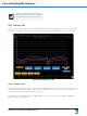
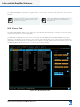
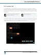
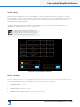
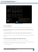
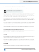
Table Of Contents
- 1. Welcome
- 2. Software Installation
- 3. Network & Firewall Overview
- 4. Lake Controller Tutorial
- 5. Home Menu Reference
- 6. EQ/Levels Menu Reference
- 7. System Store Recall Menu Reference
- 8. Modules Menu Reference
- 10. Groups Menu Reference
- 11. Solo/Mute Menu Reference
- 12. Icon Control Menu Reference
- 13. User Preferences Menu Reference
- 14. Pages Menu Reference
- 15. Network Menu Reference
- 16. Communication and Synchronization
- 17. Faults and Warnings
- 18. Analyzer Plug-in
- 19. Designer Mode Menu Reference
- 20. Lake-enabled Amplifier Reference
- 21. LM Series Reference and Operation
- 22. MY8-LAKE Reference and Operation
- 23. Keyboard Shortcuts
- 24. External Control Interfaces
- 25. Command Line Options
- 26. Firmware Update
- 27. Preset Manager
- 28. IP Address Reference
- 29. Corporate Information

Lake Controller Operation Manual Rev 1.5.9
Lake-enabled Amplier Reference
263
20.9.6.3 Voice Coil Temperature
The VOICE COIL TEMPERATURE row indicates the estimated loudspeaker voice coil temperature from the
LoadSmart test results. This is calculated from the LoadSmart verication results and Fingerprint data.
The ALL column summarizes temperatures in the
order Min/Average/Max. e.g. 20/23/25 = voice coil
temperatures in range 20° C to 25° C, with an
average value of 23° C.
20.10 Output Tab
The Module control page is selected by tapping the OUTPUT tab in Module view.
The Control tab displays data contained in the Module output DSP channel, and not the power channels. It is
important to remember that AMPLIFIER GAIN and ISVPL data are stored within each Module DSP channel
alongside other Lake Module data. Appropriate AMPLIFIER GAIN and ISVPL data are transferred to the
respective power output channel/s when they are routed to the Module outputs.
Custom RPM conguration can result in power
output channels having unique actual ISVPL values
even though they are routed from the same DSP
channel.