
Lake Controller Operation Manual
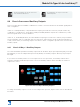
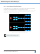
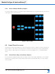
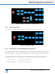
Table Of Contents
- 1. Welcome
- 2. Software Installation
- 3. Network & Firewall Overview
- 4. Lake Controller Tutorial
- 5. Home Menu Reference
- 6. EQ/Levels Menu Reference
- 7. System Store Recall Menu Reference
- 8. Modules Menu Reference
- 10. Groups Menu Reference
- 11. Solo/Mute Menu Reference
- 12. Icon Control Menu Reference
- 13. User Preferences Menu Reference
- 14. Pages Menu Reference
- 15. Network Menu Reference
- 16. Communication and Synchronization
- 17. Faults and Warnings
- 18. Analyzer Plug-in
- 19. Designer Mode Menu Reference
- 20. Lake-enabled Amplifier Reference
- 21. LM Series Reference and Operation
- 22. MY8-LAKE Reference and Operation
- 23. Keyboard Shortcuts
- 24. External Control Interfaces
- 25. Command Line Options
- 26. Firmware Update
- 27. Preset Manager
- 28. IP Address Reference
- 29. Corporate Information

170
Lake Controller Operation Manual Rev 1.5.9
Module File Types & Lake LoadLibrary™
9.4.2 Classic 3-Way and 3-Auxiliary Outputs
The signal paths for both of these Module types look similar, but the Classic 3-Way (shown in Module A)
has a single crossover page providing specic frequency bands from each output.
The 3-Auxiliary Outputs Module provides three full-bandwidth channels per Module. Each of these outputs
can be congured independently as required using traditional high-pass and low-pass lters, which are
available on each independent Auxiliary Output page.
Figure 9-3: Classic 3-Way and 3-Auxiliary Outputs
The Classic 2-Way, Classic/Linear Phase 2-Way +
1-Auxiliary Outputs, Classic/Linear Phase 3-Way,
and Classic 3-Auxiliary Outputs Modules can be
used in any combination on all available Modules.