
Lake Controller Operation Manual
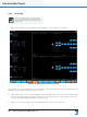
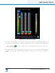
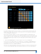
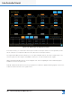
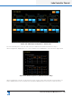
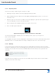
Table Of Contents
- 1. Welcome
- 2. Software Installation
- 3. Network & Firewall Overview
- 4. Lake Controller Tutorial
- 5. Home Menu Reference
- 6. EQ/Levels Menu Reference
- 7. System Store Recall Menu Reference
- 8. Modules Menu Reference
- 10. Groups Menu Reference
- 11. Solo/Mute Menu Reference
- 12. Icon Control Menu Reference
- 13. User Preferences Menu Reference
- 14. Pages Menu Reference
- 15. Network Menu Reference
- 16. Communication and Synchronization
- 17. Faults and Warnings
- 18. Analyzer Plug-in
- 19. Designer Mode Menu Reference
- 20. Lake-enabled Amplifier Reference
- 21. LM Series Reference and Operation
- 22. MY8-LAKE Reference and Operation
- 23. Keyboard Shortcuts
- 24. External Control Interfaces
- 25. Command Line Options
- 26. Firmware Update
- 27. Preset Manager
- 28. IP Address Reference
- 29. Corporate Information

Lake Controller Operation Manual Rev 1.5.9
Lake Controller Tutorial
37
Figure 4-20: Four-Channel Input Mixer
The number of inputs preset in the input mixer is relevant to the number of inputs available simultaneously
for the device / module combination, and allows the inputs to be selected or mixed together appropriately.
4. Tap the exit button in the bottom-right corner of the Input Mixer pop-up window to return to the
I/O CONFIG screen.
Each output can be custom congured by the user. Tap one of the zoom icons (represented by a magnify-
ing glass) on the right side of the Module’s block diagram. This action will open the Output Conguration
window.