
Lake Controller Operation Manual
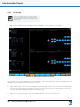
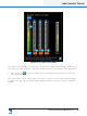
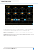
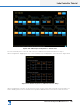
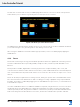
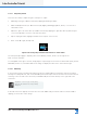
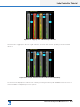
Table Of Contents
- 1. Welcome
- 2. Software Installation
- 3. Network & Firewall Overview
- 4. Lake Controller Tutorial
- 5. Home Menu Reference
- 6. EQ/Levels Menu Reference
- 7. System Store Recall Menu Reference
- 8. Modules Menu Reference
- 10. Groups Menu Reference
- 11. Solo/Mute Menu Reference
- 12. Icon Control Menu Reference
- 13. User Preferences Menu Reference
- 14. Pages Menu Reference
- 15. Network Menu Reference
- 16. Communication and Synchronization
- 17. Faults and Warnings
- 18. Analyzer Plug-in
- 19. Designer Mode Menu Reference
- 20. Lake-enabled Amplifier Reference
- 21. LM Series Reference and Operation
- 22. MY8-LAKE Reference and Operation
- 23. Keyboard Shortcuts
- 24. External Control Interfaces
- 25. Command Line Options
- 26. Firmware Update
- 27. Preset Manager
- 28. IP Address Reference
- 29. Corporate Information

36
Lake Controller Operation Manual Rev 1.5.9
Lake Controller Tutorial
4.3.5 I/O Cong
This section assumes the use of classic routing
mode; all providing extensive I/O routing options.
The MY8-LAKE in simplied view provides a xed
output cong.
1. Tap the I/O CONFIG button to display the block diagrams of each Module in the Frame.
Figure 4-19: LM 26 I/O Conguration Screen
The right side of the I/O CONFIG page can be dragged to scroll up and down for viewing of all Module block
diagrams where all diagrams cannot t on the screen.
2. Tap any black space within the block diagram area and drag up or down to scroll. The I/O CONFIG page
is interactive; each blue processing block can be selected to directly access the relevant screen in the
software. Each block diagram has a front-end input mixer.
3. Tap any one of the four inputs of the ‘My 3-Way’ Module to access the input mixer.