
Lake Controller Operation Manual
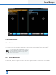
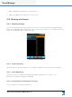

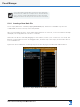
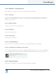
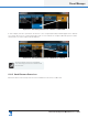
Table Of Contents
- 1. Welcome
- 2. Software Installation
- 3. Network & Firewall Overview
- 4. Lake Controller Tutorial
- 5. Home Menu Reference
- 6. EQ/Levels Menu Reference
- 7. System Store Recall Menu Reference
- 8. Modules Menu Reference
- 10. Groups Menu Reference
- 11. Solo/Mute Menu Reference
- 12. Icon Control Menu Reference
- 13. User Preferences Menu Reference
- 14. Pages Menu Reference
- 15. Network Menu Reference
- 16. Communication and Synchronization
- 17. Faults and Warnings
- 18. Analyzer Plug-in
- 19. Designer Mode Menu Reference
- 20. Lake-enabled Amplifier Reference
- 21. LM Series Reference and Operation
- 22. MY8-LAKE Reference and Operation
- 23. Keyboard Shortcuts
- 24. External Control Interfaces
- 25. Command Line Options
- 26. Firmware Update
- 27. Preset Manager
- 28. IP Address Reference
- 29. Corporate Information

Lake Controller Operation Manual Rev 1.5.9
Preset Manager
307
Figure 27-1: Preset Manager Default State
27.2 Screen Layout
27. 2 .1 Main Area
The main area is divided into four columns labeled ABCD in Figure 22 1. By default, columns A&B display
the contents for the presets folder located on the computer and Columns C&D show the online Frames.
The current directory path is displayed above column A
/ C when COMPUTER is selected. The Preset Manager
stores this location upon exiting the program, and
restores it when restarted.
27.2.2 Button Bar Interface
The button bar, labeled E in Figure 27-1 follows the same logic as the Lake Controller, three colors indicate
the button status.
▸ ORANGE - currently selected function