
Lake Controller Operation Manual
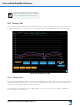
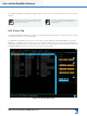
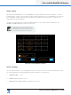
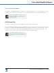
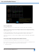
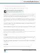
Table Of Contents
- 1. Welcome
- 2. Software Installation
- 3. Network & Firewall Overview
- 4. Lake Controller Tutorial
- 5. Home Menu Reference
- 6. EQ/Levels Menu Reference
- 7. System Store Recall Menu Reference
- 8. Modules Menu Reference
- 10. Groups Menu Reference
- 11. Solo/Mute Menu Reference
- 12. Icon Control Menu Reference
- 13. User Preferences Menu Reference
- 14. Pages Menu Reference
- 15. Network Menu Reference
- 16. Communication and Synchronization
- 17. Faults and Warnings
- 18. Analyzer Plug-in
- 19. Designer Mode Menu Reference
- 20. Lake-enabled Amplifier Reference
- 21. LM Series Reference and Operation
- 22. MY8-LAKE Reference and Operation
- 23. Keyboard Shortcuts
- 24. External Control Interfaces
- 25. Command Line Options
- 26. Firmware Update
- 27. Preset Manager
- 28. IP Address Reference
- 29. Corporate Information

258
Lake Controller Operation Manual Rev 1.5.9
Lake-enabled Amplier Reference
The SELECT/DESELECT ALL button toggles states to either select or deselect all channels on the selected
Module.
With a single channel selected, clicking the graph
will display the time and sample number for that
sample on the status line.
A white dot is displayed on the graphs if a power
cycle of the Frame was performed during the
sampling period.
20.8 Events Tab
The MODULE EVENTS tab shown in Figure 20-7 lists all faults and warnings occurring in the power output
channels allocated to the selected Module.
The EVENT LOG displayed on this screen is the same as that displayed via GLOBAL EVENTS with lters
applied to only display events relevant to the currently selected Module, power output channels assigned to
that Module, and the Frame/s incorporating those channels. The tab is identical in format and function to the
GLOBAL EVENTS tab. Please refer to section 20.12 for further details.
Figure 20-7: Module Events Tab