
Lake Controller Operation Manual
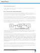
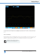
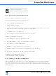
Table Of Contents
- 1. Welcome
- 2. Software Installation
- 3. Network & Firewall Overview
- 4. Lake Controller Tutorial
- 5. Home Menu Reference
- 6. EQ/Levels Menu Reference
- 7. System Store Recall Menu Reference
- 8. Modules Menu Reference
- 10. Groups Menu Reference
- 11. Solo/Mute Menu Reference
- 12. Icon Control Menu Reference
- 13. User Preferences Menu Reference
- 14. Pages Menu Reference
- 15. Network Menu Reference
- 16. Communication and Synchronization
- 17. Faults and Warnings
- 18. Analyzer Plug-in
- 19. Designer Mode Menu Reference
- 20. Lake-enabled Amplifier Reference
- 21. LM Series Reference and Operation
- 22. MY8-LAKE Reference and Operation
- 23. Keyboard Shortcuts
- 24. External Control Interfaces
- 25. Command Line Options
- 26. Firmware Update
- 27. Preset Manager
- 28. IP Address Reference
- 29. Corporate Information

Lake Controller Operation Manual Rev 1.5.9
Analyzer Plug-in
221
Phase Normal / Phase Alternate
On the default Phase display plot, all phase values are plotted within a 360° range of +180° to –180°, with
0° in the center [wrapped phase]. This 360° range represents one complete cycle of delay at any given
frequency. You can also choose to view the phase within a 360° range of 0° to 360° (alternate phase). This
is useful if there is a reverse of signal polarity within your transfer function measurement setup. Please refer
to your analyzer documentation for further information regarding phase and the implementation of these
options.
18.4.4.10 Invert
Pressing the INVERT button swaps the inputs to the Transfer Function calculation, so the analyzer divides
the reference signal by the measurement signal. This feature is mainly used when you want to display the
inverse (upside‐down) magnitude response curve of an EQ or processor channel to facilitate using the room
or system response as a template for setting EQ lters.
Figure 18-18: Invert enabled