
Lake Controller Operation Manual
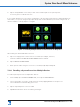
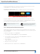
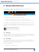
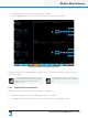
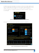
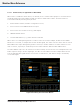
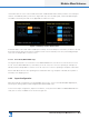
Table Of Contents
- 1. Welcome
- 2. Software Installation
- 3. Network & Firewall Overview
- 4. Lake Controller Tutorial
- 5. Home Menu Reference
- 6. EQ/Levels Menu Reference
- 7. System Store Recall Menu Reference
- 8. Modules Menu Reference
- 10. Groups Menu Reference
- 11. Solo/Mute Menu Reference
- 12. Icon Control Menu Reference
- 13. User Preferences Menu Reference
- 14. Pages Menu Reference
- 15. Network Menu Reference
- 16. Communication and Synchronization
- 17. Faults and Warnings
- 18. Analyzer Plug-in
- 19. Designer Mode Menu Reference
- 20. Lake-enabled Amplifier Reference
- 21. LM Series Reference and Operation
- 22. MY8-LAKE Reference and Operation
- 23. Keyboard Shortcuts
- 24. External Control Interfaces
- 25. Command Line Options
- 26. Firmware Update
- 27. Preset Manager
- 28. IP Address Reference
- 29. Corporate Information

Lake Controller Operation Manual Rev 1.5.9
Modules Menu Reference
121
2. Select a Module icon in the work area, and tap I/O CONFIG
The I/O CONFIG button is active only when a Module is selected in the work area.
Figure 8-2: LM 26 I/O Conguration Screen
Figure 8-2 shows the I/O CONFIG page for an LM 26. The sections that follow describe each screen/func-
tion in further detail.
I/O Cong settings are stored in system congura-
tion les and in Frame/system presets. I/O Cong
parameters are transferred during the Frame
Replace function.
I/O Cong parameters are not stored, recalled,
copied, or pasted via Module or base conguration
les.
8. 2 .1 Digital Clock Conguration
LM, PLM+ and D Series devices provide two digital clock domains:
▸ The Primary Digital Clock locks to sample rates of 48, 96, or 192 kHz.
▸ The Sample Rate Converter (SRC) Clock locks to 44.1, 48, 88.2, 96, 176.4, and 192 kHz.