
Operation Manual
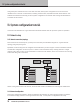
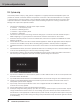
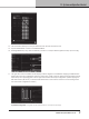
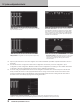
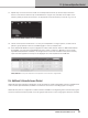
Table Of Contents

12. Lake Processing and Lake Controller
32
D SERIES Lake Operation Manual rev 3.0.1
11.6.4. Indication
The LoadPilot feature constantly monitors the impedances at the two given pilot tone frequencies and compares to
the measured thresholds. The following faults and warnings can be triggered.
• Speaker shorted warning – Both tones below lower threshold. Corresponds to a distant short circuit that can
either be in the cabling or in the speaker.
• Speaker damaged warning – One of the tones is below or above thresholds. Corresponds to an unexpected
impedance deviation of one of the tones, most likely a damage to the speaker.
• Under speaker count warning – Both tones above upper threshold. Corresponds to an impedance increase
across the impedance response and most likely a loss of speaker(s) in a parallel speaker connection.
• No load fault – At least one tone above measurable area or signicantly above upper threshold. Most likely
corresponding to loss of the load.
• Short circuit fault – LoadPilot analysis below short circuit threshold.
12. Lake Processing and Lake Controller
12.1. Introduction
D Series Lake integrates seamlessly into the Lake Processing environment, providing all features, functionality and
connectivity associated with all Lake Processors. The internal Lake Processing, which includes programmable
crossovers, EQ, dynamics and other functions, is fully controllable via Lake Controller software with a version
number of v6.3 for D 200:4L, D 120:4L and D 80:4L, v6.5.0 for D 20:4L and D 10:4L and v6.5.1 for D 40:4L.
All models are compatible with newer versions of the Lake Controller.
Additional information is available in the Lake Controller Operation Manual and Lake Network Conguration Guide,
both available on www.labgruppen.com. Also, additional documentation is available from the Start Menu after
software installation.
Visit http://labgruppen.com to download the latest software, rmware and documentation for your devices.
12.2. Modules and Frames
A Frame represents one physical Lake Processor device (e.g. a D 200:4L). A maximum of four Modules are
contained within each Frame; these are referred to as Module A, B, C and D. The number of Modules shown in a
given Frame is dependent upon the signal processing conguration of that Frame.
ed as a Classic Crossover (Bessel, Butterworth, Linkwitz–Riley), as a Linear Phase
Contour Classic 1 Way (CL1–Way) Output Modules, providing a total of four Module outputs that can be routed
to any of the four power outputs, but default is one to one (input 1 -> output 1 etc.). Please refer to the Lake
Controller Operation Manual for further information.