
Operation Manual
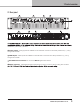
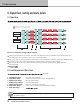
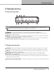
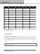
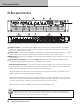
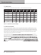
Table Of Contents

9. Front panel interface
16
D SERIES Lake Operation Manual rev 3.0.1
Table 9.1: LED/category chart
OFF Green Amber Red
Frame
N/A Frame OK Frame warning Frame fault
Temp
N/A Temp OK Temp warning Temp fault
PSU
N/A PSU OK
Power supply/
Mains warning
Power supply/
Mains fault
Power
No mains power
Fixed:ON
Blinking: Turning ON
Button pressed.
Hold for transition
Fixed: STANDBY
Blinking: Turning to
STANDBY
Load
No LoadPilot active
LoadPilot active
and LoadOK
Load warning Load fault
Amp
N/A Power channel OK Power channel warning Power channel fault
Signal
Output below signal
present threshold (–60 dB)
Output above signal
present threshold (–60 dB) input clip (–2 dB) or limit/fault active
Mute
Inactive channel in
bridge operation
Unmuted
Lake module is muting the
signal chain at either input
router, module input or
module output
Power channel muted
Select
Frame not selected Frame selected Waiting for more touches N/A
Input signal approaching Input signal clip
9.3. Frame select and ID
9
SELECT LED and TOUCH BUTTON – Selects mode and indicates control between computer software and
unit. A single touch on the button will select the unit in supported computer software views. Multiple consecutive
touches will select the corresponding Lake module (one touch for module A, 2 for module B etc.). In the other
direction, when selecting the unit in a supported computer software view, the LED will indicate the unit is selected
with steady green illumination.
NOTE: The touch buttons use capacitive touch technology and might be sensitive to large temperature
and humidity variations.