
Lake Controller Operation Manual Version 1.7.0


Lake Controller Operation Manual Rev 1.7.0
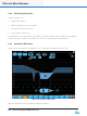
EQ/Levels Menu Reference
75
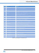
Label Function Description
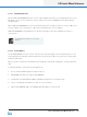
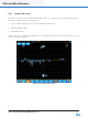
K Band Meter The band meter will display RMS level with a wide green bar, display peak level
with a thin green bar, and peak hold with a wide orange segment.
The total RMS and peak limiting gain reduction is indicated with an orange bar
that moves downward as gain reduction increases.
When the Limiter is bypassed, the gain reduction meter changes to striped
grey, indicating the amount of gain reduction that would have been applied to
the signal if the limiter was inserted.
L Module Output
Meter
The band meter will display RMS level with a wide green bar, peak level with a
thin green bar, and peak hold with a wide orange segment.
The total RMS and peak limiting gain reduction is indicated with an orange bar
that moves downward as gain reduction increases.
Table 6-2: Function Description for Multiband Conguration Screen
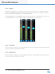
6.2.4 Enable Mute
This button locks and unlocks the mute buttons and is active by default (that is, muting or unmuting is
allowed). When the button is active (orange), channel muting via the Controller is enabled. When the button
is inactive (blue), channel muting is disabled.
6.2.5 Enable Polarity
This button locks or unlocks the polarity buttons and is inactive by default (polarity buttons locked). When
the button is active (orange), the polarity can be changed. When the button is inactive (blue), the polarity
cannot be changed.
If a system designer has locked polarity changes on
one or more outputs, the polarity button for the
outputs will not be displayed in User mode.