
Lake Controller Operation Manual
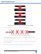
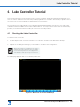
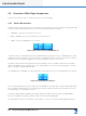
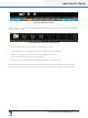
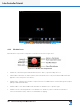
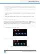
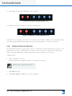
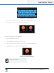
Table Of Contents
- 1. Welcome
- 2. Software Installation
- 3. Network & Firewall Overview
- 4. Lake Controller Tutorial
- 5. Home Menu Reference
- 6. EQ/Levels Menu Reference
- 7. System Store Recall Menu Reference
- 8. Modules Menu Reference
- 10. Groups Menu Reference
- 11. Solo/Mute Menu Reference
- 12. Icon Control Menu Reference
- 13. User Preferences Menu Reference
- 14. Pages Menu Reference
- 15. Network Menu Reference
- 16. Communication and Synchronization
- 17. Faults and Warnings
- 18. Analyzer Plug-in
- 19. Designer Mode Menu Reference
- 20. Lake-enabled Amplifier Reference
- 21. LM Series Reference and Operation
- 22. MY8-LAKE Reference and Operation
- 23. Keyboard Shortcuts
- 24. External Control Interfaces
- 25. Command Line Options
- 26. Firmware Update
- 27. Preset Manager
- 28. IP Address Reference
- 29. Corporate Information

32
Lake Controller Operation Manual Rev 1.5.9
Lake Controller Tutorial
Figure 4-10: LM 26 Frame Placed in Main Work area
4.3.2 Module Icons
Each Module icon provides conguration information as shown in Figure 4-11.
Figure 4-11: Module Icon Components
▸ Module ID - Identies a particular Module within the device, represented by this icon.
▸ Frame Label - Identies the Frame (device) associated with this icon by a user-dened label that also
appears on the front panel of the device.
▸ Module Type - Identies the number of output channels or an abbreviation of a Module type description
(MEq for a Mesa EQ Module).
▸ Module Label - User-dened label that describes the Module’s use or speaker type.
▸ Module Selection and Clip Indicator - The Module icon border is yellow to indicate the Module is
selected. If it ashes red, a channel on that Module is clipping.