
Lake Controller Operation Manual
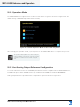
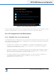
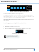
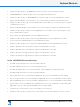
Table Of Contents
- 1. Welcome
- 2. Software Installation
- 3. Network & Firewall Overview
- 4. Lake Controller Tutorial
- 5. Home Menu Reference
- 6. EQ/Levels Menu Reference
- 7. System Store Recall Menu Reference
- 8. Modules Menu Reference
- 10. Groups Menu Reference
- 11. Solo/Mute Menu Reference
- 12. Icon Control Menu Reference
- 13. User Preferences Menu Reference
- 14. Pages Menu Reference
- 15. Network Menu Reference
- 16. Communication and Synchronization
- 17. Faults and Warnings
- 18. Analyzer Plug-in
- 19. Designer Mode Menu Reference
- 20. Lake-enabled Amplifier Reference
- 21. LM Series Reference and Operation
- 22. MY8-LAKE Reference and Operation
- 23. Keyboard Shortcuts
- 24. External Control Interfaces
- 25. Command Line Options
- 26. Firmware Update
- 27. Preset Manager
- 28. IP Address Reference
- 29. Corporate Information

288
Lake Controller Operation Manual Rev 1.5.9
MY8-LAKE Reference and Operation
22.2 Operation Mode
The MY8-LAKE device supports three modes for Host device recognition as shown in Figure 22-4. The
default setting of MY8-AE96 provides full functionality.
Figure 22-4: Card ID Operation Mode for Host data recognition
After changing the operation mode, cycle the power on the MY8-LAKE device to complete the process.
The Operation Mode parameter is unaffected by the
recall of a Module or System le, or by the resetting
of a Frame to default Contour or Mesa congura-
tions.
22.3 Host Analog Output Reference Conguration
To ensure that limiter levels in the LoadLibrary Module les remain compliant with the MY8-LAKE device,
an additional option will be available via the I/O CONFIG entitled ANALOG OUTPUT REFERENCE.
Analog Output Reference provides limiter compensation options as shown in Figure 22-5.