
Lake Controller Operation Manual
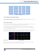
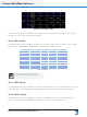
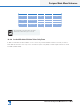
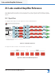
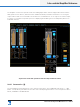
Table Of Contents
- 1. Welcome
- 2. Software Installation
- 3. Network & Firewall Overview
- 4. Lake Controller Tutorial
- 5. Home Menu Reference
- 6. EQ/Levels Menu Reference
- 7. System Store Recall Menu Reference
- 8. Modules Menu Reference
- 10. Groups Menu Reference
- 11. Solo/Mute Menu Reference
- 12. Icon Control Menu Reference
- 13. User Preferences Menu Reference
- 14. Pages Menu Reference
- 15. Network Menu Reference
- 16. Communication and Synchronization
- 17. Faults and Warnings
- 18. Analyzer Plug-in
- 19. Designer Mode Menu Reference
- 20. Lake-enabled Amplifier Reference
- 21. LM Series Reference and Operation
- 22. MY8-LAKE Reference and Operation
- 23. Keyboard Shortcuts
- 24. External Control Interfaces
- 25. Command Line Options
- 26. Firmware Update
- 27. Preset Manager
- 28. IP Address Reference
- 29. Corporate Information

Lake Controller Operation Manual Rev 1.5.9
Lake-enabled Amplier Reference
255
▸ STATUS - OK is displayed when all load detection and monitoring functions report that the load attached
to the power output channel is normal. If output conditions are such that a fault or warning state arises, a
message will be displayed here advising the nature of the problem. Please refer to the associated Operation
Manual for a list of fault/warning messages.
▸ LoadPilot status (PLM+ and D Series only). LoadPilot is congured via the separate CAFÉ software applica-
tion. Not available for PLM Series ampliers.
20.6.6 Power Output Data Block
6
The bottom display block provides user feedback about the performance of the device. The information is
(from top):
▸ AMPLIFIER - Conrms Frame label and channel number. The channel number corresponds to the
power output channel. The Frame name and number are separated by a colon.
▸ STATUS - OK is displayed during normal operation, when no faults, warnings or clipping is occurring. If
an amplier-related fault or warning state arises, a message is displayed here indicating the problem.
▸ TPSU - Provides the temperature of the power supply. The temperature is expressed as a percentage of
the maximum safe value.
▸ TCH - Provides the temperature of the particular channel’s output stage, displayed as a percentage of
the maximum safe value.
▸ TAMP - Whichever of TPSU or TCH is closer to the maximum temperature allowed is also displayed on
a horizontal bar graph.
20.6.7 Mute and Polarity Enable
Controls to the right of the channel strips enable and disable the MUTE and POLARITY functions on a global
basis. When MUTE is enabled (default), the mute buttons are active. When MUTE is disabled, the mute
status cannot be changed.
Polarity control allows three states:
▸ HIDDEN (default) removes the polarity buttons from the channel strips.
▸ VISIBLE displays the polarity buttons but they are disabled.
▸ ENABLED activates the buttons and allows a change of state.