
Lake Controller Operation Manual
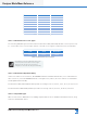
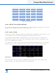
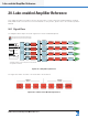
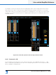
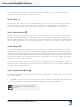
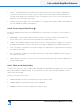
Table Of Contents
- 1. Welcome
- 2. Software Installation
- 3. Network & Firewall Overview
- 4. Lake Controller Tutorial
- 5. Home Menu Reference
- 6. EQ/Levels Menu Reference
- 7. System Store Recall Menu Reference
- 8. Modules Menu Reference
- 10. Groups Menu Reference
- 11. Solo/Mute Menu Reference
- 12. Icon Control Menu Reference
- 13. User Preferences Menu Reference
- 14. Pages Menu Reference
- 15. Network Menu Reference
- 16. Communication and Synchronization
- 17. Faults and Warnings
- 18. Analyzer Plug-in
- 19. Designer Mode Menu Reference
- 20. Lake-enabled Amplifier Reference
- 21. LM Series Reference and Operation
- 22. MY8-LAKE Reference and Operation
- 23. Keyboard Shortcuts
- 24. External Control Interfaces
- 25. Command Line Options
- 26. Firmware Update
- 27. Preset Manager
- 28. IP Address Reference
- 29. Corporate Information

250
Lake Controller Operation Manual Rev 1.5.9
Lake-enabled Amplier Reference
20. Lake-enabled Amplier Reference
This chapter describes information specic using the Lake Controller with Lake-enable ampliers including
PLM, PLM+ and D Series devices. For further details on each product, please refer to the relevant Operation
Manual.
20.1 Signal Flow
The diagrams below depict the audio signal ow for Lake-enabled ampliers.
Input
Mixer A
Input
Mixer B
Input
Mixer C*
Input
Mixer D
Input
Routers
1-4*
WITH
INPUT
MUTES
Output Routing
AES 1-4
Analog 1-4
*INPUTS
Dante 1-8
(no mutes)
*OUTPUTS
Dante Receivers 1-8
AES/Analog
pass thru
to Dante
* PLM Series is limited to 2 Inputs, 2 Outputs and 2 Contour Modules
^ Not applicable for PLM Series
Lake Contour
Module A
Lake Contour
Module B
Lake Contour
Module C*
Lake Contour
Module D*
Module Data stored in Module Files (Speaker Presets)
Frame Data stored in System Files and Frame Presets
Attenuator
Mute
Phase Rev
Custom RPM^
Attenuator
Mute
Phase Rev
Custom RPM^
Attenuator
Mute
Phase Rev
Custom RPM^
Attenuator
Mute
Phase Rev
Custom RPM^
LoadPilot^
LoadPilot^
LoadPilot^
LoadPilot^
ISVPL
Auto RPM^
ISVPL
Auto RPM^
ISVPL
Auto RPM^
ISVPL
Auto RPM^
Amp Gain
Amp Gain
Amp Gain
Amp Gain
LoadSmart
LoadSmart
LoadSmart
LoadSmart
Figure 20-1: Amplier Signal Flow
The signal ow within the Lake Contour Module is shown below.
Figure 20-2: Lake Contour Module Signal Flow