
Lake Controller Operation Manual
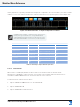
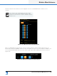
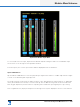
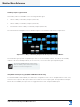
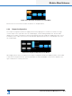
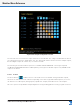
Table Of Contents
- 1. Welcome
- 2. Software Installation
- 3. Network & Firewall Overview
- 4. Lake Controller Tutorial
- 5. Home Menu Reference
- 6. EQ/Levels Menu Reference
- 7. System Store Recall Menu Reference
- 8. Modules Menu Reference
- 10. Groups Menu Reference
- 11. Solo/Mute Menu Reference
- 12. Icon Control Menu Reference
- 13. User Preferences Menu Reference
- 14. Pages Menu Reference
- 15. Network Menu Reference
- 16. Communication and Synchronization
- 17. Faults and Warnings
- 18. Analyzer Plug-in
- 19. Designer Mode Menu Reference
- 20. Lake-enabled Amplifier Reference
- 21. LM Series Reference and Operation
- 22. MY8-LAKE Reference and Operation
- 23. Keyboard Shortcuts
- 24. External Control Interfaces
- 25. Command Line Options
- 26. Firmware Update
- 27. Preset Manager
- 28. IP Address Reference
- 29. Corporate Information

Lake Controller Operation Manual Rev 1.5.9
Modules Menu Reference
141
Figure 8-20: Module Input Mixer
To connect/disconnect an input, tap the button labeled ON/OFF or drag the fader. The total Module input
mix is shown on the far right of the Input Mixer window.
For Dante inputs, the receiver input channel label is displayed below the ON button.
Input +4dBu Button
Tap the INPUT +4dBu button to view the physical input signal meter relative to +4 dBu. Tap the button again
to return to the default Digital Clip (DClip) view.
The DClip metering mode shows the audio level prior to any gain adjustment (input headroom, or digital gain
offset), and indicates when the A/D converters will clip. The +4 dBu metering mode shows the audio level
after any gain adjustment, and is useful for comparing levels of different input signals prior to processing.
This is a global function; all physical input meters throughout the system display the reference selected here.