
Lake Controller Operation Manual
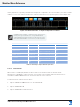
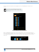
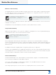
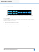
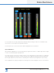
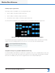
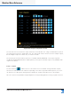
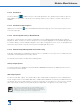
Table Of Contents
- 1. Welcome
- 2. Software Installation
- 3. Network & Firewall Overview
- 4. Lake Controller Tutorial
- 5. Home Menu Reference
- 6. EQ/Levels Menu Reference
- 7. System Store Recall Menu Reference
- 8. Modules Menu Reference
- 10. Groups Menu Reference
- 11. Solo/Mute Menu Reference
- 12. Icon Control Menu Reference
- 13. User Preferences Menu Reference
- 14. Pages Menu Reference
- 15. Network Menu Reference
- 16. Communication and Synchronization
- 17. Faults and Warnings
- 18. Analyzer Plug-in
- 19. Designer Mode Menu Reference
- 20. Lake-enabled Amplifier Reference
- 21. LM Series Reference and Operation
- 22. MY8-LAKE Reference and Operation
- 23. Keyboard Shortcuts
- 24. External Control Interfaces
- 25. Command Line Options
- 26. Firmware Update
- 27. Preset Manager
- 28. IP Address Reference
- 29. Corporate Information

Lake Controller Operation Manual Rev 1.5.9
Modules Menu Reference
139
Dual redundancy status is also displayed on the Front
Panel of the device (except D Series)
8.2.6 Iso-Float Status & AES Termination
When an online device is selected the button reads Analog Iso-Float & AES Termination. When any virtual
device or an MY8-LAKE device is selected then neither option is available.
The Analog Iso-Float & AES Termination Status screen is accessed by tapping the zoom button to the left of
this summary as shown in Figure 8-17.
Figure 8-17: Analog Iso-Float & AES Termination Summary
Software control of the Analog Iso-Float is available for Lake-enabled ampliers, along with separate control
for the analog outputs on LM Series devices. AES Termination is available for all devices except MY8-LAKE.
The current status is identied by an orange button as shown in Figure 8-18.
Figure 8-18: LM Series Analog Iso-Float & AES Termination Status
8.2.7 Input Mix Summary and Input Mixers/Switches
Input mix summaries and switches are shown on the I/O CONFIG page as part of the interactive signal path
for each Module.