
Technology Brief Understanding Relationships Voltage-Current-Impedance


WWW.LABGRUPPEN.COM
Technology Brief: Designing for Great Performances
High impedance 70 V amplier outputs are congured for a maximum
of 70.7 V
RMS
(with headroom that’s 100 V
PEAK
) and the matching high
impedance speakers are designed to reach their rated power at
70.7 V. Connect the speakers (as many as required to cover area) to
the amplier so long as the total load is kept below the total power
capability of the amplier.
For high impedance loads we set amplier peak voltage to 100 V
PEAK
so the 70.7 V
RMS
voltage is not exceeded.
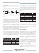
CPL Current Peak Limiter
Another LAB GRUPPEN amplier conguration and protection
feature is offered with CPL or the Current Peak Limiter. CPL is an
indicator for maximum amplier output current. The trigger is based
on the output transistors which have limits on the amount of current
they can safely source and the CPL limiter will ash the front panel
LED when the maximum current draw is approaching. The LED will
change to a steady orange and the channel will mute when high
output current & voltage in excess of the output limit is sensed. will
hold the channel muted until the load and/or input gain is reduced and
peak current is below the protection threshold. In situations where
the load impedance is not known CPL is a useful indicator (producing
a steady orange LED) for sensing when the amplier is near the
maximum load or is experiencing extremely low load impedance.
The CPL circuit cycles every 6 seconds and if the load returns to a
state that’s within predetermined limits, the amplier channel will
automatically resume operation. CPL does not affect program signals
when driving a properly matched load.
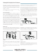
Amplifier Setup
If system gain is properly congured and sufcient headroom (the
difference in dB between operating level and maximum output or clip
level) has been factored into the design, then the maximum peaks in
the program material will be reproduced without clipping.
FIGURE 7
This is important because all audio devices in the signal chain
contribute to the system’s ultimate sound quality and, clipping
anywhere in the signal chain cannot be corrected elsewhere in the
chain.
LAB GRUPPEN C Series ampliers can be congured to limit the
output voltage with a variety of gain settings to match a nominal
input level.
This enables the system designer to optimize the amplier Gain
Structure, allowing for the desired operating headroom.
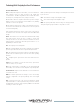
Figure 7 shows this design approach. Our 4-ohm speaker is rated at
600 W maximum average power and 1200 W maximum peak power.
If we select the LAB GRUPPEN C 68:4 amplier we can expect
1700 W with headroom. High level dynamic music program’s V
PEAK
can reach levels of 3 to 10 times V
RMS
corresponding to +10 to +20 dB
of required headroom to avoid amplier clipping and prior to reaching
the speaker’s maximum power handling. The powers and voltages in
dBu for this gain structure are shown.
Example: if we want our mixer output signal at 0 dBu to provide our
nominal operating power of 450 W we will set the amplier gain to
+35 dB. The amplier then has 6 dB of headroom before it clips and
we set the VPL switch to 141 V corresponding to 1700 W at 4-ohms.
The mixer has 20 dB of headroom before it clips.
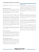
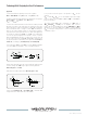
FIGURE 8
LAB GRUPPEN C Series ampliers have input gain settings in
3 dB steps from +23 dB to +44 dB. This broad range of gain settings
provides great exibility in conguring the amplier to ensure you can
match the nominal input level for maximum headroom.
5
FIGURE 9
Amplifier Protection
First and foremost, the LAB GRUPPEN is founded on the design
and manufacture of exceptionally reliable amplers that deliver the
highest quality sound. Whether permanently installed or on the road
touring they are great and consistent performers.