
Data Sheet

WWW.LABGRUPPEN.COM
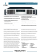
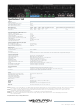
Specifications C 5:4X
General
Number of channels 4
Peak total output all channels driven 500 W
Peak output voltage per channel 100 V
Max. output current per channel 5.6 Arms
Max. Output Power
16 ohms
8 ohms 4 ohms 2 ohms
Hi-Z 70 Vrms/100 V peak Hi-Z 100 Vrms/141 V peak Hi-Z 140 Vrms/200 V peak
Per ch. (all ch.’s driven) 125 W 125 W 125 W 60 W
125 W n.a. n.a.
Bridged per ch. 250 W 250 W 125 W n.r.
1)
n.a. n.a 250 W
Performance with Gain: 32 dB and VPL: 100 V
THD 20 Hz - 20 kHz for 1 W <0.1%
THD at 1 kHz and 1 dB below clipping <0.05%
Signal To Noise Ratio >112 dBA
Channel separation (Crosstalk) at 1 kHz >70 dB
Frequency response (1 W into 8 ohms) +0/-3 dB 6.8 Hz - 34 kHz
Input impedance 20 kOhm
Common Mode Rejection (CMR) >50 dB, 20 Hz to 20 kHz
Output impedance @ 100 Hz 48 mOhm
Voltage Peak Limiter (VPL), max. peak output
VPL, selectable per ch. (V)
2)
100, 63, 45, 32 V
VPL, selectable when bridged (V)
2) 3)
200, 126, 90, 64 V
Voltage Peak Limiter mode (per ch.) Hard / Soft
Gain and Level
Amplifier gain selectable (all channels)
3)
– rear-panel switches
29, 32, 35, 38 dB
Default gain 32 dB
Level adjustment (per ch.) Front-panel potentiometer, 21 position detented from -inf to 0 dB, hidden behind security panel/dust filter grille
Connectors and switches
Input connectors (per ch.) 3-pin Phoenix, electronically balanced
Output connectors (per ch.) Barrier strip 2-pole screw terminals
Output bridge mode A+B, C+D, E+F, G+H, inputs A, C, E, G are signal source
High pass filter Fixed at 35 Hz, switchable per channel
NomadLink
®
network On board, 2 x RJ45 connectors, IN and OUT
Intelligent fans (on/off) Yes, depending on presence of output signal
Power on/off and Remote enable on/off Individual switches on front panel
Cooling Two fans, front-to-rear airflow, temperature controlled speed
General Purpose Outputs (GPO) Contact Closure types, 2-pole Phoenix
General Purpose Inputs (GPI) Contact Closure types, 2-pole Phoenix
Front-panel indicators
Common NomadLink Network; Power Average Limiter (PAL)
4)
; Power on
Per channel
Signal present / High-impedance; Voltage Peak Limiter (VPL); Current Peak Limiter (CPL):
Very High Frequency (VHF); High temperature; Fault; Mute
Power
Operating voltage, 230 V / 115 V nominal Universal power supply 65-265 V
Minimum power-up voltage, 230 V / 115 V 80 V
Power Average Limiter (PAL)
4)
Yes
Power Factor Correction (PFC) Yes
Soft start / Inrush current draw Yes / max. 5 A
Mains connector IEC Inlet
Dimensions W: 483 mm (19”), H: 88 mm (2 U), D: 343 mm (13.5”)
Weight 8.5 kg (18.75 lbs.)
Finish Black painted steel chassis with gray painted steel front
Approvals CE, ANSI/UL 60065 (ETL), CSA C22.2 NO. 60065, FCC
Note 1): Regarding n.r. (not recommended) notes: The amplifier will be fully operational in bridge-mode into 2 ohm and high impedance (Hi-Z) loads, but due to physical constraints in
the construction, the max. output power will not be significantly higher than running individual channels and therefore this mode of operation is not recommended.
Note 2): For sine waves, peak voltage output values translate to Vrms with the formula V/1.41 = Vrms. E.g. 100 V peak equals app. 70 Vrms. Hence, outputs can be set for
high-impedance loads without requiring a transformer.
Note 3): Automatic -6 dB gain compensation when bridging channels. Ch.’s A+B and/or C+D, can be bridged individually.
Note 4): PAL can reduce the maximum output power to keep the power supply operating safely, and/or to prevent excessive current draw tripping the mains breaker.
Refer to Operation Manual.
All specifications are subject to change without notice.
Item no. TDS-C54X_V10 - 30.11.2015