
Technology Brief Understanding Relationships Voltage-Current-Impedance

WWW.LABGRUPPEN.COM
Technology Brief: Designing for Great Performances
Speaker Impedance
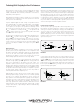
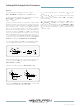
Let’s look at voltages and currents for various speaker impedances
and powers. Figure 6 shows an 8 ohm load driven with 100 watts of
power.
4
FIGURE 6
Low Impedance speakers are typically in the range of 2 ohms to
16 ohms. The ratio of voltage to current (V/I) remains constant for the
same load. As the speaker load decreases for a given amplier power
the voltage (V
RMS
) decreases and the current (I
RMS
) increases. This
may appear to be a simple concept but in reality it is something that
many commercial grade ampliers do not adequately address. That’s
because delivering high voltage for high impedance systems and
high current for low impedance systems, with 4 separate channels,
all within the same compact 2U chassis, presents some real
performance challenges for the amplier designer. It necessitates
added protection features and demands the highest quality
components. It begins with the power supply which is the heart of
an amplier and C-Series are designed to continuously produce full
output without “sag” or diminished output during demanding high
current operation with low impedance speakers and, with the change
of the rear panel DIP switches, the same channel swings the voltage
for high impedance output that remains constant ensuring peak
performance in distributed systems.
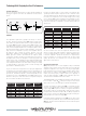
To give you an idea of how important it is to specify an amplier that
can deliver the power under all conditions let’s look at the differences
in voltage and current for a low impedance system using two different
power levels, 100 W & 1000 W with 2, 4 & 8 ohm impedances. Note
the differences in the voltage V
RMS
and Current I
RMS
requirements to
deliver the same power. In the rst reference it requires 3.5 amps at
28 volts to deliver 100 W into an 8 ohm load.
Amplifier Power Load Impedance Voltage V
rms
Current I
RMS
100 W 8 ohm 28 V 3.5 A
100 W 4 ohm 20 V 5.0 A
100 W 2 ohm 14 V 7.0 A
1000 W 8 ohm 90 V 11.1 A
1000 W 4 ohm 63 V 16.0 A
1000 W 2 ohm 45 V 22.0 A
Decrease the speaker load to 2 ohms, which is the minimum safe
operating level and it requires 7 amps at 14 volts to deliver the same
100 watts. Nothing else has changed, only the load impedance. Now
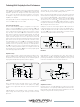
let’s look at the requirements for a Constant Voltage system using
the 70.7 and 100 V
RMS
outputs with different load impedances. Here
the output voltage remains constant and the output current (which is
much lower than with low impedance systems) varies by load for a
given power:
As these numbers show there are signicant differences in the
amount of current and voltage required to deliver the target power
in low and high impedance systems. A quality amplier design
is therefore required to provide an assortment of comprehensive
protection features for consistent operation with the best sound
quality, day after day. Let’s examine some of these features and
apply what we have learned.
VPL Voltage Peak Limiter
VPL greatly enhances the C Series amplier’s utility for individual
channels used in mixed systems that require both low and high
impedance amplication in a single unit. Selecting the appropriate
peak voltage limit for the load ensures the amplier operates at the
highest levels yet within its limits. VPL is an effective protection
feature that when properly congured reduces the triggering of
either the high temperature or CPL current peak limiter protection
circuits that mute individual channels when active.
The LAB GRUPPEN C Series amplier’s peak output voltage limits may
be set to values of 1.414 x V
RMS
to limit power output. To set the limits
all we need to know is the required power and the load impedance.
To match the amplier to speaker load, VPL is congured with DIP
switches on the rear panel in 8 steps from 30% to 100% of maximum
output voltage. VPL may be set to hard or soft clip limit and enables
safe operation with low or high impedance loads. There are 3 green
front panel LEDs that indicate -4 dB, -10 dB, -40 dB input signal levels
that’s useful for selecting the appropriate input gain for driving the
attached load and to achieve the target SPL.
Front panel red LED’s will illuminate when VPL is active. There’s also
a second red SIG | HI-IMP LED that, when illuminated along with the
VPL LED, indicates a shorted load has been detected which requires
remedial action.
Amplifier Power Load Impedance Voltage V
rms
Current I
RMS
10 W 500 ohm 70.7 V 0.14 A
25 W 20 0 ohm 70.7 V 0.35 A
50 W 100 ohm 70.7 V 0.71 A
100 W 50 ohm 70.7 V 1.4 A
1000 W 5 ohm 70.7 V 14.14 A
10 W 1000 ohm 100 V 0.1 A
25 W 40 0 ohm 100 V 0.25 A
50 W 200 ohm 100 V 0.5 A
100 W 100 ohm 100 V 1.0 A
1000 W 10 ohm 10 0 V 10.0 A