
Technology Brief Understanding Relationships Voltage-Current-Impedance


WWW.LABGRUPPEN.COM
Technology Brief: Designing for Great Performances
At this point the electro-acoustic system should provide the target
sound levels. If we add signal processing capabilities to ensure
reliable, maintainable and consistent performance we’ll achieve a
high quality sound experience.
What amplier performance features should you look for and how
will they effect the conguration of the entire system? Let’s rst look
at the system’s electrical design.
A power amplier applies an audio voltage to a speaker and for a
given load impedance a certain power will be drawn. If our amplier
can limit the speaker voltage to ‘V
MAX
’, which would deliver ‘P
MAX
’
to the speaker, we can protect the speaker from damage caused
by excessive power. We may also choose to limit output voltage to
‘V
NOM
’ to maintain the nominal power ‘P
NOM
’ to the speaker. At all
times our goal is to deliver the correct power to produce the desired
level ‘dB
SPL
’ at the listener position.
Another system consideration is the required input signal level to the
amplier ‘dB
NOM
’ to produce the power ‘P
NOM
’ at the speaker and the
desired ‘dB
SPL
’ at the listening position. As a matter of convention,
designers will choose 0 dBu or +4 dBu as the nominal input signal
to drive a system to nominal SPL levels. Using the amplier’s gain
control you can adjust for ‘V
NOM
’ at the output for a given ‘dB
NOM
’
input level.
Electrical Types
There are two amplier congurations used to drive commercial
speaker systems; they are high impedance or low impedance. Each
has distinct performance advantages and both may be appropriate
for use in the same venue. Both deliver amplier power to the
speakers but the difference is in the way they drive the connected
loads including speaker(s) and the interconnecting cable(s).
Large scale, low impedance systems deliver high current and are
intended for high quality, high SPL applications. Stage productions
and concert performances will always use high current, low
impedance speaker systems that are congured to service a few
speakers and to deliver the maximum power. Longer speaker cables
will dissipate more amplier output current so the available power at
the speaker will decrease proportionally. Low impedance systems
use large gauge speaker cables that are as short as possible to
efciently deliver maximum amplier power.
High impedance systems, also known as constant voltage systems,
deliver high peak voltages, typically 70 V or 100 V and are generally
used for low to moderate SPL applications. These systems use
large quantities of installed speakers as typically found in airports,
hotels and convention centers and they may have hundreds of feet
of speaker cable connecting them to the amplier. The resistance of
these long speaker lines combined with the characteristic reactive
load produced by many attached speakers requires high constant
voltage to drive the line, compensating for cable loss while delivering
the maximum power.
Mixed use of low and high impedance systems can be found in venues
such as cinemas or theme parks. The low impedance speakers are
used for sound reinforcement in the presentation spaces and separate
high impedance systems are used for the speakers that deliver
voice paging and background music in lobbies, rest rooms or other
non-presentation spaces. Ampliers such as the LAB GRUPPEN
C Series are a great choice for these permanent installations because
they service both low and high impedance speaker systems from a
common 2 rack-space unit with 4 separate channels.
Power, Signals and Ohms
The two system types, high impedance and low impedance, each
have different electrical requirements. A proper system design for
either type necessitates calculating for voltage, power and dB values.
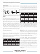
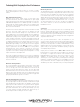
To solve for these we use Ohm’s law.2 Ohm’s law and the power
denition describe the current through and the voltage across a
speaker relating the power in the load to current, voltage, and load
resistance. Figure 4 shows the currents and voltages and provides
expressions for power.
FIGURE 4
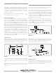
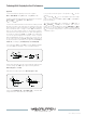
In most speaker specication sheets you will see different types of
rating voltages listed. The voltage across the speaker can be described
as peak or RMS values, where ‘peak’ refers to the maximum vale and
‘RMS’ can be thought of as a time average measure of the power
producing effect of the signal voltage. Figure 5 shows the differences
between peak and RMS values for a single note (sine wave) and for
typical musical program signals.
3
FIGURE 5