
DeviceControl Operation Manual
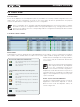
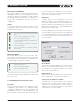
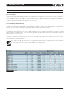
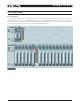
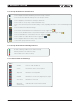
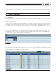
Table Of Contents
- FRONT PAGE
- 1 CONTENTS
- 2 DEVICECONTROL INTRODUCTION
- 3 INSTALLING THE DEVICECONTROL APPLICATION
- 4 CONNECTING YOUR PC TO NOMADLINK
- 5 QUICK GUIDE FOR BASIC FUNCTIONS
- 5.1 Uploading Subnet(s)
- 5.2 Toolbars overview
- 5.3 Start Here
- 5.3.1 Basic operations
- 5.3.2 Lock mode
- 5.3.3 Creating Channel Groups
- 5.3.4 Creating Power Groups
- 5.3.5 Naming (or renaming) Devices, Channels and Groups
- 5.3.6 Saving the configuration file
- 5.3.7 Opening a saved system configuration file
- 5.3.8 Reconnecting to a subnet
- 5.3.9 Establishing Secure Connections
- 5.3.10 Synchronization
- 5.3.11 Normal operation with devices matched and synchronized
- 6 REFERENCE SECTION

24 DeviceControl Operation Manual
Model and Serial Number
The model number is entered automatically when
uploading a subnet into the configuration, or when
creating or editing a configuration. Serial numbers
are uploaded from the network only, and are en-
tered on the Configuration side when a match is
established.
Status
This column indicates the status on devices in the
Configuration and on the Physical network. Status
indications are as follows:
Not connected but associated with physical
device
Device outside configuration (Online state)
Not connected to physical device
Connected with a physical device but parameters
not synchronized
Connected with a physical device with para-
meters synchronized
Device is firmware uncontrollable, possible
firmware fault
DIP-switch Match
DIP-switch Match is active only in the Online state.
The indicator color represents the status of detected
Physical DIP-switch settings when compared to the
corresponding Configuration settings.
DIP-switch match OK
DIP-switch mismatch warning
DIP-switch mismatch fault
DIP-switch status warnings and faults are discussed
in Section 6.7.3.
6.4.3 Editing Functions in Device View
Overview
DeviceControl provides tools for creating an offline
configuration “from scratch”, or for editing an existing
configuration. With these tools, you can create a “vir-
tual amplifier system” for a specific application. The
pre-configured “virtual system” then can be matched
to the new physical configuration. DeviceControl’s
match function ensures that the physical amplifier
racks were configured correctly.
Add Device
To add a device to the configuration, click on the
Add Device button on the toolbar. Alternatively, you
may select “Add new device” from the Edit menu,
right-click and select from pop-up menu, or press the
Alt+D keys. An “Add Device” command displays this
pop-up window (Figure 6.8).
Select the amplifier type. If the device is to be placed
in a new subnet, select this option. A new subnet will
be created automatically. The device will be placed
in the first open position in the existing subnet or in
the new subnet.
Figure 6.7
Insert Device
This function is similar to Add Device, except the new
device is inserted immediately before the currently
selected device. The position numbers of succeeding
devices are increased by one.
Replace Device
This function is similar to Add Device, except the new
device replaces the currently selected device.
Copy, Paste, and Paste to subnet…
You may select any device and use the Copy and
Paste functions to replace another device with the
copied device type and name. Use the “Paste to
subnet” menu command to paste the selected and
copied device into a new subnet.
6 reference section