
DeviceControl Operation Manual
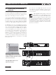
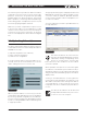
Table Of Contents
- FRONT PAGE
- 1 CONTENTS
- 2 DEVICECONTROL INTRODUCTION
- 3 INSTALLING THE DEVICECONTROL APPLICATION
- 4 CONNECTING YOUR PC TO NOMADLINK
- 5 QUICK GUIDE FOR BASIC FUNCTIONS
- 5.1 Uploading Subnet(s)
- 5.2 Toolbars overview
- 5.3 Start Here
- 5.3.1 Basic operations
- 5.3.2 Lock mode
- 5.3.3 Creating Channel Groups
- 5.3.4 Creating Power Groups
- 5.3.5 Naming (or renaming) Devices, Channels and Groups
- 5.3.6 Saving the configuration file
- 5.3.7 Opening a saved system configuration file
- 5.3.8 Reconnecting to a subnet
- 5.3.9 Establishing Secure Connections
- 5.3.10 Synchronization
- 5.3.11 Normal operation with devices matched and synchronized
- 6 REFERENCE SECTION

DeviceControl Operation Manual 7
4.2 Determining preferred
connection type
You may connect your DeviceControl host computer
to the NomadLink Network using either a direct
(peer-to-peer) connection, or via a LAN (Local
Area Network). A LAN requires inserting a router
or network switch, with or without wireless (WiFi)
capability. Either a peer-to-peer or a LAN connection
will work with a single NLB 60E (one subnet); a LAN
is normally required for connection to more than one
NLB 60E (multiple subnets).
4.2.1 Peer-to-peer connection (using crossed
RJ45 cable)
In this configuration, a dedicated TCP/IP connection is
made directly to the NLB 6 0E using only an Ethernet
cable. This type of connection may be preferable in
these applications:
Temporary connections for setup or maintenance
•
of an NLB 60E when functioning as a self-standing
unit; operation is via front panel or GPI
Permanent connections between one NLB 60E •
and a computer dedicated to the DeviceControl
application.
In this configuration, a dedicated TCP/IP connection
is made directly to the NLB 60E. A peer-to-peer
connection ensures that no other network devices are
inserted between the computer and the NLB 60E.
If a dedicated connection is established, no
other network connections will be available
through the assigned Ethernet port. How-
ever, if the computer also has multiple
Ethernet ports or a wireless LAN connection, these
remain available for other uses such as Internet ac-
cess.
4.2.2 LAN connection (wired via “straight”
RJ45 cables or via wireless)
A LAN connection is required if the system configura-
tion requires more than one subnet, as each subnet
is controlled by a dedicated NLB 60E.
A LAN connection may be preferred in some ap-
plications even if only one subnet is required. If the
host computer is needed for Internet access via the
Ethernet port, or for controlling other networked de-
vices, a LAN connection avoids any need to manually
reset the TCP/IP configuration when switching from
DeviceControl to another application. If the network
router offers DHCP assignment (now common even
in inexpensive models), then the NLB 60E can be
set to automatically accept a network address from
the router.
A separate, third-party network device must
be accommodated in the system to create
a LAN connection. This could raise reli-
ability issues, particularly in touring applica-
tions. Any network devices should be chosen with
this consideration in mind.
4.3 Establishing a peer-to-peer
connection
4.3.1 Physical connection
Connect the PC to the NLB 60E using an Ethernet
cable. A crossed cable should be used for peer-
to-peer connections; however, many newer PCs
may allow peer-to-peer connection using a standard
(“straight”) Ethernet cable (Figure 3.1).
Two Ethernet ports are provided on the NLB 60E:
one on the front panel and one on the rear panel (the
front panel port is primarily for temporary setup and
service use). Both ports are active but only one can
be used at a time.
4.4 Maximum cable lengths
Maximum cable length allowed between the Device-
Control host PC and the NLB 60E (or LAN network
device) conforms to standard Ethernet specification
of 100 meters.
The maximum cable length in between any intercon-
nected NLB 60E and an amplifier may not exceed
300 meters. Total cable length for links in between
all amplifiers in one subnet may not exceed 100
meters.
As a result, in a non-closed-loop daisy-chained subnet,
the total maximum cable length is 400 meters (300
+ 100), and in a closed loop subnet the maximum
cable length is 700 meters (300 + 300 + 100).
connectinG Your Pc to noMADlinK 4