
DeviceControl Operation Manual
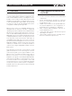
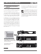
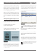
Table Of Contents
- FRONT PAGE
- 1 CONTENTS
- 2 DEVICECONTROL INTRODUCTION
- 3 INSTALLING THE DEVICECONTROL APPLICATION
- 4 CONNECTING YOUR PC TO NOMADLINK
- 5 QUICK GUIDE FOR BASIC FUNCTIONS
- 5.1 Uploading Subnet(s)
- 5.2 Toolbars overview
- 5.3 Start Here
- 5.3.1 Basic operations
- 5.3.2 Lock mode
- 5.3.3 Creating Channel Groups
- 5.3.4 Creating Power Groups
- 5.3.5 Naming (or renaming) Devices, Channels and Groups
- 5.3.6 Saving the configuration file
- 5.3.7 Opening a saved system configuration file
- 5.3.8 Reconnecting to a subnet
- 5.3.9 Establishing Secure Connections
- 5.3.10 Synchronization
- 5.3.11 Normal operation with devices matched and synchronized
- 6 REFERENCE SECTION

6 DeviceControl Operation Manual
4.1 Establishing a Nomadlink
network
You must establish the NomadLink Network before
you connect the DeviceControl host computer. If you
have done so already, proceed to Section 4.2.
Connecting the NLB 60E to Lab.gruppen amplifiers in
a NomadLink network is a simple and straightforward
procedure. All connections are made with standard
(“straight”) Ethernet-type cables equipped with RJ45
connectors. Cable grade should be Cat-5 or better.
The NLB 60E connects to the amplifiers through the
two rear panel ports labeled NOMADLINK IN and
OUT. Using a standard (“straight”) Ethernet cable,
connect the OUT port on the NLB 6 0E to the IN port
on the first amplifier in the network. Next, connect
the OUT port of the first amplifier to the IN port of
the second amplifier. Continue to “daisy chain” the
amplifiers, connecting the OUT port to the IN port of
the next amplifier, until all amplifiers are connected.
Complete the network loop by connecting the OUT
port of the last amplifier to the IN port on the NLB
60E (Figure 4.1).
The OUT port of the NLB 60E must be connected
to the IN port of the first amplifier to allow the De-
viceControl software to correctly identify devices
on the network.
IMPORTANT NOTE: Within restricted
cable distances, the NomadLink network
will function as a single-ended daisy chain
without closing the loop. (The loop is closed
by connecting the last amplifier’s OUT port back to
the NLB 6 0Es IN por t). However, it is strongly recom-
mended that the loop be completed: doing so provides
a redundant signal path and improves communication
speed on the network
4 connectinG Your Pc to noMADlinK
Crossed RJ45 cable between NLB 60E
and PC. If NLB 60E is connected to switch
of HUB, use "straight" cable. PC can also be
connected on front-panel.
"Straight" RJ45 cables between
NLB 60E and amplifiers.
Figure 4.1