
DeviceControl Operation Manual
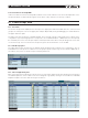

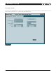

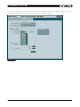


Table Of Contents
- FRONT PAGE
- 1 CONTENTS
- 2 DEVICECONTROL INTRODUCTION
- 3 INSTALLING THE DEVICECONTROL APPLICATION
- 4 CONNECTING YOUR PC TO NOMADLINK
- 5 QUICK GUIDE FOR BASIC FUNCTIONS
- 5.1 Uploading Subnet(s)
- 5.2 Toolbars overview
- 5.3 Start Here
- 5.3.1 Basic operations
- 5.3.2 Lock mode
- 5.3.3 Creating Channel Groups
- 5.3.4 Creating Power Groups
- 5.3.5 Naming (or renaming) Devices, Channels and Groups
- 5.3.6 Saving the configuration file
- 5.3.7 Opening a saved system configuration file
- 5.3.8 Reconnecting to a subnet
- 5.3.9 Establishing Secure Connections
- 5.3.10 Synchronization
- 5.3.11 Normal operation with devices matched and synchronized
- 6 REFERENCE SECTION

DeviceControl Operation Manual 33
The DIP-switches tab (Figure 6.14) displays DIP-switch positions of the configured device and the matched
physical device, if any. Physical device status is shown only when power is on. Positions of DIP-switches may
be changed on a configured “virtual” device by clicking on them. Any resulting mismatch is indicated by a red
fault or yellow warning LED. The Power and sensitivity calculator shows output power and input sensitivity for
the configured DIP-switch settings. Refer to specific amplifier Operation Manuals for more information.
Figure 6.14
Position of physical amplifier DIP-switches cannot be changed by DeviceControl.
reference section 6