
DeviceControl Operation Manual
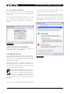
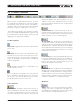

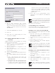
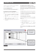
Table Of Contents
- FRONT PAGE
- 1 CONTENTS
- 2 DEVICECONTROL INTRODUCTION
- 3 INSTALLING THE DEVICECONTROL APPLICATION
- 4 CONNECTING YOUR PC TO NOMADLINK
- 5 QUICK GUIDE FOR BASIC FUNCTIONS
- 5.1 Uploading Subnet(s)
- 5.2 Toolbars overview
- 5.3 Start Here
- 5.3.1 Basic operations
- 5.3.2 Lock mode
- 5.3.3 Creating Channel Groups
- 5.3.4 Creating Power Groups
- 5.3.5 Naming (or renaming) Devices, Channels and Groups
- 5.3.6 Saving the configuration file
- 5.3.7 Opening a saved system configuration file
- 5.3.8 Reconnecting to a subnet
- 5.3.9 Establishing Secure Connections
- 5.3.10 Synchronization
- 5.3.11 Normal operation with devices matched and synchronized
- 6 REFERENCE SECTION

12 DeviceControl Operation Manual
5.2 Toolbars overview
DeviceControl is organized around a set of views
accessible by selecting buttons on the main toolbar.
The different views access various configuration,
operation, and monitoring functions. More detailed
information is given in the Reference Section 6.
The Toolbar is grouped into four segments; Toolbar,
Select View, Mode and Edit bar. Each segment may
be independently repositioned by clicking on and
dragging to the respective end bars.
Toolbar segment:
Full screen: Toggles between full screen and reduced
screen view.
Tree View: The Tree View is open by default on the
left side of the screen when opening DeviceControl.
This view shows the current network configuration
(either as uploaded or created offline), including all
subnets and groups.
Lock: Engages operational or configuration lock
modes in DeviceControl
Blue icon indicates configuration lock only; yellow is
both configuration and operational lock. Lock type
can be set in the Settings dialog in the File menu.
For detailed instruction see Section 6.2.
Select view bar:
Device View: The Device View shows the list of
devices (amplifiers). The left side of the list displays
the virtual configured devices, with the power on/
off switch indicated for each device. The right side
(Physical) displays the detected devices in the
subnets. Center “link” indicator between left and
right shows Match status between configured and
physical devices.
Channel View: The Channel View shows all con-
figured channels as derived from the Device list. In
this view you may add or delete Channel Groups, and
assign channels to new or existing groups.
Groups View: The Groups View is generated from
the selections made in the Channel list. The All and
Subnet Groups are automatically generated during
upload from the subnet(s) and cannot be modified.
The Groups View is the primary screen for monitoring
status, faults and warnings, as well as for controlling
mute and solo functions.
Power View: The Power View displays all devices in
the system and allows grouping of selected devices
for powering on and off as a group with a single
button click. The entire system and all connected
subnets are default Power Groups.
Details View: The Details View shows parameter
details for the selected channel or device (amplifier
or NLB 60E), including DIP-switch settings, perfor-
mance indicators such as level and temperature,
and a sensitivity calculator for power and sensitivity
calculation dependent on configured settings.
Mode bar:
Offline: When not connected to a physical subnet,
editing of an offline configuration is possible. You
may add devices, add groups, rename channels and
devices, and set configured DIP-switches.
5 QuicK GuiDe for BAsic functions