
Install Instructions


Page 50
LAARS Heating Systems
SECTION 10
MAINTENANCE
WARNING
Disconnect all power to the unit before attempting any
service. Contact with electricity can result in severe
injury or death.
10.A System Maintenance
Do this once a year, unless otherwise noted.
1. Lubricate all the pumps in the system, per the
instructions on the pump.
2. Inspect the venting system for obstruction or leakage.
Periodically clean the screens in the vent terminal and
combustion air terminal (when used).
3. Remove and inspect the air lter. Clean with soapy
water if needed. Be sure that lter is dry before re-
inserting back into air lter box. Replace air lter if
damaged.
4. Keep the area around the unit clear and free of
combustible materials, gasoline, or other ammable
vapors or liquids.
5. If the unit is not going to be used for extended periods
in locations where freezing normally occurs, it should
be isolated from the system and completely drained of
all water.
6. Low water cutos, if installed, need to be checked
every 5 years. Float type low water cutos should be
ushed periodically.
7. Inspect and clean the condensate collection, oat
switch and disposal system yearly.
8. When a means is provided to neutralize condensate,
ensure that the condensate is being neutralized
properly.
9. Inspect the ue passages, and clean them using
brushes or vacuums, if necessary. Sooting in ue
passages indicates improper combustion. Determine
the cause of the problem and correct it.
10. Inspect the vent system and air intake system, and
ensure that all joints are sealed properly. If any joints
need to be resealed, completely remove the existing
sealing material, and clean with alcohol. Apply new
sealing material, and reassemble.
11. The Pressure Relief Valve should be inspected and
tested every year.
10.B Maintenance and Component
Description
Use only genuine Manufacturer replacement parts.
CAUTION
Label all wires prior to disconnection when servicing
controls. Wiring errors can cause improper and
dangerous operation. Verify proper operation after
servicing.
The gas and electric controls in the unit are engineered
for long life and dependable operation, but the safety of
equipment depends on their proper functioning. Only a
qualied service technician should inspect the basic items
listed below every year:
a. Unit controls f. Flow switch
b. Automatic gas valve g. Low water cuto
c. Pressure switches h. Burner
d. Blower i. Heat exchanger
e. Pump
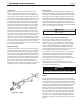
Burner
Check the burner for debris. Remove the blower arm
assembly to access the burner. Remove the four bolts
connecting the blower to the arm. (See Figure 47.) Remove
the ve bolts which hold the burner arm in place. Pull
the burner up and out. Clean the burner, if necessary, by
blowing compressed air from the outside of the burner into
the center, and wipe the inside clean with glass cleaner. A
dirty burner may be an indication of improper combustion
or dirty combustion air. Determine the cause of this, and
correct it. If the burner gasket is damaged, replace it when
replacing the burner.
NOTE: When installing the burner, make sure the
ange is aligned with the mating surface, as each is
keyed to control the t.
Modulating Gas Valve / Venturi
The modulating gas valve consists of a valve body that
incorporates the On/O gas ow control and a negative
pressure regulator. It provides the air/gas ratio control in
combination with the Venturi to the unit. It is designed to
operate with a gas supply pressure between 4 and 13
inches w.c. To remove the gas valve and/or Venturi, shut o
the 120 Volt power supply to the boiler. Turn o all manual
gas valves connecting the boiler to the main gas supply
line. Remove the front door of the boiler to gain access to
the gas valve and Venturi. Disconnect the four ange bolts
connecting the gas manifold pipe to the gas valve. Remove
the electrical connections to the gas valve. Remove the
bolts connecting the Venturi ange to the blower. This
allows the entire gas valve and Venturi assembly to be
removed to facilitate inspection and cleaning.
Reassemble the valve/Venturi assembly in reverse order,
making sure to include all gaskets and O-rings. Turn on
the manual gas valves and check for gas leaks. Turn on
the 120 Volt power. Place the unit in operation following
the instructions in Section 9. Once the boiler is operating.
check for leaks again and conrm that all fasteners are
tight.
Check the unit setup according to Section 9.