
Install Instructions


Page 46
LAARS Heating Systems
Control Settings for Lead Lag System - Part 2
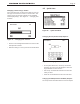
1. On the Lead Lag Master, set the setpoint used by the
Lead Lag system.
How to get there: From the “Home” screen, press “I” to
go to “Info/Install.” Choose “Advanced Setup,” then go
to “Lead/ Lag Conguration.” Select “Lead Lag Master
Conguration,” and go to the line for “Setpoint.”
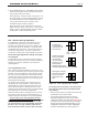
2. On the Lead Lag Master, set the Base Load to match
the number of boilers in the system. We mentioned
the Base Load setting in the explanation of the “Lead
Lag Modulation Cycle.” Whenever the heating demand
causes the active burner(s) to run faster than the Base
Load value, the Lead Lag system will put an additional
burner on line. The Base Load value depends on the
number of boilers in the system:
Note that you only need to enter the Base Load value on
the Lead Lag Master.
How to get there: From the “Home” screen, press “I” to
go to “Info/Install.” Choose “Advanced Setup,” then go
to “Lead/ Lag Conguration.” Select “Lead Lag Master
Conguration.” Go to the line for “Base Load Common
Rate.”
8.N About Lead Lag Operation
(continued)
8.O Adjusting CO
2
1. Measure the CO
2
/O
2
in the ue products at high
re.
The Unit can be forced to high re to allow
for easier setup. The controller has a feature that
makes it easy to go directly to the high re condition.
The unit will operate at high re for 5 minutes, then
modulate down automatically.
How to get there: From the “Home” screen,
press “I” to go to “Info/ Install.” Choose “Test,” then
go to “Forced Rate.” Select “Set High Fire,” then
select “Start Test.”
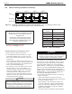
The CO
2
readings should be between the values
shown in Table 19. If the CO
2
is not within the range
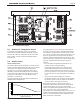
shown, adjustments may be made. To adjust the
high re CO
2
, locate the high re adjuster screw
according to the appropriate gure. Slowly make
adjustments in 1/16 of a revolution increments until
the CO
2
is within the range identied.
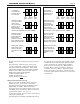
2. Measure the CO
2
/O
2
in the ue products at low
re.
Unit can be forced to low re to allow for easier
setup.
How to get there: From the “Home” screen, press
“I” to go to “Info/ Install.” Choose “Test,” then go to
“Forced Rate.” Select “Set High Fire,” then select
“Start Test.”
The CO
2
readings should be between the values
shown in Table 19. If the CO
2
is not within the range
shown, adjustments may be made. To adjust the low
re CO
2
, locate the low re adjuster screw according
to the appropriate gure. Slowly make adjustments
in 1/16 of a revolution increments until the CO
2
is
within the range identied.
3. Repeat steps 1 and 2 to conrm that the CO
2
ranges
are within the required ranges. Adjust if necessary.
4. Conrm that the dierential pressure is still within
the appropriate range.
5. If any of the measurements cannot be adjusted
to the specied ranges or the CO levels are
above 150ppm when adjusted, please consult
the factory for further information.
WARNING
Improper adjustment may lead to poor combustion
quality, increasing the amount of carbon monoxide
produced. Excessive carbon monoxide levels may
lead to personal injury or death.