
Install Instructions


Page 45
NEOTHERM Residential Boilers
HIGH EFFICIENCY RESIDENTIAL BOILERS
®
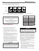
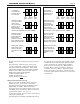
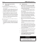
Figure 34. Lead / Lag Operation, 3 boilers. Figure 35. Lead / Lag Operation, 4 or more boilers.
Low demand -
The first boiler in
sequence fires at
less than 65%
First
boiler
Second
boiler
Third
boiler
Fourth
boiler
Demand increases -
Once the first boiler
reaches 65%,
the second boiler
switches on, and
both modulate
together between 20%
and 65% (this can be adjusted up to 25% to 85%).
Demand increases -
Once the first two
boilers reach 65%,
the third boiler
switches on, and all
three modulate together
between 20% and 65%
Nearing max. demand -
The fourth boiler is
active. Once all four
reach 65%, all are
allowed to go over
65%
* - The Lead/Lag controller will change the firing order of the boilers,
based on the run time of each burner.
Low demand -
The first boiler in
sequence fires at
less than 65%
First
boiler
Second
boiler
Third
boiler
Demand increases -
Once the first boiler
reaches 65%,
the second boiler
switches on, and
both modulate
together between 25%
and 65% (this adjustable up to 25% and 85%)
Demand increases -
Once the first two
boilers reach 65%,
the third boiler
switches on, and all
three modulate together
between 25% and 65%
Nearing max. demand -
Once all three reach
65%, then all three
are allowed to go over
65%
* - The Lead/Lag controller will change the firing order of the boilers,
based on the run time of each burner.
identify each unit as a Follower by turning on “Follower
Enable.”
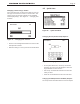
How to get there: From the “Home” screen, press
“I” to go to “Info/Install.” Choose “Advanced Setup,”
then go to “Lead/ Lag Conguration”. Select “Lead
Lag Follower Conguration.” On the line for “Follower
Enable” select “Enable.” When you select Follower
Enable these options will be displayed
“Enable via Modbus Master” or
“Enable via Sola Master”.
Choose “Enable via Sola Master”.
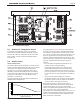
Wiring Connections for Lead Lag -
Now you can make the Modbus wiring connections
between the units. The controller in each boiler
includes two wiring terminals for the Modbus system,
labeled “MB1” and “MB2.” MB1 has the wiring
connections to the User Interface display on each unit,
and MB2 is used to communicate with the other boilers
in the Lead Lag system. See Figure 17.
To reach the controller, open the cabinet of the boiler by
removing the plastic bezel.
The wiring from the controller on the rst boiler runs to
the controller on the next boiler. Use 22 AWG or thicker
shielded twisted-pair wire with drain. Two twisted pairs
or three conductors are needed. Wire A on MB2 of
Boiler 1 must be connected to A on MB2 of Boiler 2,
wire B on Boiler 1 goes to B on Boiler 2, and wire C
on Boiler 1 goes to C on Boiler 2. Repeat this wiring
for any other boilers in the system. Connect all of the
drain wires and ground the drain wire on one end of the
assembly only.