
Install Instructions


Page 34
LAARS Heating Systems
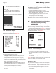
8.C The Home Display
When the boiler is operating normally, the controller will
display the Home display. See Figure 21.
Figure 21. - Home Display
The Home Display has three sections:
• The upper section (customizable) displays the most
important operating information for the unit. In the
example shown here, the display is showing the system
setpoint, the operating temperature, the outlet and inlet
temperatures for the water entering and leaving the
boiler, and the outdoor temperature.
• The central section shows some additional operating
and setup information. In this case, this area lists the
boiler name, boiler state, current demand, and the
current password level (the “access status”).
• The lower section shows any current lockouts, holds,
or alerts.
8.D Customizing your Home Display
To customize the upper section of your Home Display
• Press “I” Info/Install button
• Scroll to highlight “Display Setup”, press OK
• Highlight the line you would like to change,(example
”Line 2 Operating Temp”), press OK
• Scroll to highlight the parameter that you do want
displayed and then press OK. The new parameter is
now displayed on the Home Display.
Repeat this step for the other parameters, if desired.
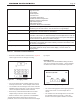
8.E Entering/Changing Control Settings
Info/Install Display (including
PASSWORDS)
The Info/Install Display is where you will start every time.
All of your Controls, Diagnostics, Setups, and more, are
accessed starting with the Info/Display screen.
• From the Home display shown in Figure 21, press the “I”
button (“Info/ Install”). The display will change to show the
six sub-menus available. See Figure 22.
Figure 22. - Info/ Install Display
• To move from one choice to another, use the Left-
and Right-Arrow buttons or the Up- and Down-Arrow
buttons.
• Once you have highlighted the choice you want, press
the round OK
Table 17 shows the functions listed under each of the sub-
menus. For details, see Sections 8A and 8C.
Changing a Value
The procedure for changing a control value used by the
system is listed below. (In this example, we will use the
screen for the CH Setpoint.)
• Use the Up- and Down-Arrow buttons to step down
through the list until you have highlighted the correct line
on the display.
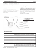
Install Op Manual
Doc# 1218G-NH.pdf
Doc# 1252-NH.pdf
(this document)
The ‘User Interface’ was updated for the
2013 model year to the EMEA display shown in
Figure 20.
For older units with the white user
interface, you will need to download the
1218G-NH.pdf from the ‘Discontinued
Documents’ on the manufacturers website.