
Install Instructions


Page 27
NEOTHERM Residential Boilers
HIGH EFFICIENCY RESIDENTIAL BOILERS
®
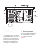
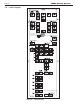
Figure 16. Control Panel Layout
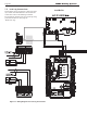
7.D Hydronic Heating Using External
Modulation Control
About External Control -
When this unit is used for hydronic heating with external
modulation control, a call for heat must be supplied to the
“T-T or Interlock” terminal. Once the call is supplied the
control starts the Boiler and System pumps and begins the
ignition process. Once in Run, the unit monitors the ame
signal, call for heat, safeties, and water temperatures.
The boiler setpoint is used to limit the maximum water
temperature leaving the boiler only. The modulation rate
is controlled by a 4-20mA signal supplied by an external
control. (This can also be 0-10Vdc using a converter -
Manufacturer part number CA006100.) When setting
up a system using an external control, take care to set
Anti-Short Cycle feature to prevent “hunting “ and possible
premature component failure.
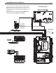
7.E Optional Field Connections
Terminal block 8 (TB8) in the control panel is used for the
‘Safety Chain’ and for connecting optional components
such as low water cutos, ow switches, additional high
limits, and other eld-supplied devices that must be
interlocked with the boiler. These are non-powered dry
contacts only. All safeties or end switches must be wired in
series by removing the supplied jumpers.
See Figure 16