
Install Instructions

Page 16
LAARS Heating Systems
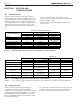
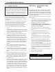
SCHED 40 METAL PIPE CAPACITY FOR 1.50 SPECIFIC GRAVITY
UNDILUTED PROPANE
NOMINAL PIPE SIZE
@
11” W.C. INLET AND 0.5” W.C. PRESSURE DROP
SIZE 1/2” 3/4” 1” 1-1/4” 1-1/2” 2”
LENGTH MAXIMUM CAPACITY IN THOUSANDS OF BTU PER HOUR
20 200 418 787 1616 2422 4664
40 137 287 541 1111 1664 3205
60 110 231 434 892 1337 2574
80 94 197 372 763 1144 2203
100 84 175 330 677 1014 1952
Table 12.
EQUIVALENT LENGTHS OF STRAIGHT PIPE FOR TYPICAL SCH 40 FITTINGS
NOMINAL PIPE SIZE
FITTING 1/2” 3/4” 1” 1-1/4” 1-1/2” 2”
LINEAR FEET
90° ELBOW 3.6 4.4 5.2 6.6 7.4 8.5
TEE 4.2 5.3 6.6 8.7 9.9 12
Table 10.
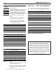
SCH 40 METAL PIPE CAPACITY FOR 0.60 SPECIFIC GRAVITY NATURAL GAS
NOMINAL PIPE SIZE
@
0.30” W.C. PRESSURE DROP
LENGTH 1/2” 3/4” 1” 1-1/4” 1-1/2” 2”
FT CUBIC FEET OF GAS PER HOUR
20 92 190 350 730 1100 2100
40 130 245 500 760 1450
60 105 195 400 610 1150
80 90 170 350 530 990
100 150 305 460 870
Table 11.
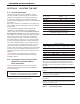
Unit
NATURAL GAS
REQUIRED
CU FT
SIZE / HR.
80 80
105 105
150 150
210 210
Table 9.
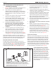
TO SIZE PIPING:
Measure linear distance from meter outlet to
last boiler. Add total input of all boilers and
divide by 1000 to obtain cu ft / hr required.
Add total equivalent length of ttings used
according to Table 10. Align total length (pipe
and ttings) on left side column of Table 11
with highest cubic feet of gas required.
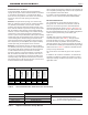
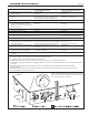
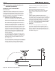
SECTION 5 PUMP REQUIREMENTS
5.A Boiler Flow and Head Requirements
TEMPERATURE RISE IN °F
20°F 25°F 30°F 35°F 40°F
FLOW H/L FLOW H/L FLOW H/L FLOW H/L FLOW H/L
SIZE GPM FT GPM FT GPM FT GPM FT GPM FT
80 7.6 14.9 6.1 10.1 5.1 7.1 4.3 5.8 3.8 4.6
105 10 23.1 8 17 6.7 12.4 5.7 9.6 5 7.6
150 14.3 28.5 11.4 19 9.5 13.6 8.1 11.2 7.1 8.8
210 20 24.1 16 16.7 13.4 11.6 11.3 9 9.9 6.9
TEMPERATURE RISE IN °C
11°C 14°C 17°C 19°C 22°C
FLOW H/L FLOW H/L FLOW H/L FLOW H/L FLOW H/L
SIZE lpm m lpm m lpm m lpm m lpm m
80 29 4.5 23 3.1 19 2.2 16 1.8 14 1.4
105 38 7.0 30 5.2 25 3.8 22 2.9 19 2.3
150 54 8.7 43 5.8 36 4.1 31 3.4 27 2.7
210 76 7.3 61 5.1 51 3.5 43 2.7 37 2.1
Table 13. Water Flow Requirements
Notes:
Consult and conrm with Applicable Fuel
Gas Code before beginning work.
Verify gas inlet pressure is between
4”
W.C. (1.0kPa)
and 13” W.C. (3.2kPa),
before and during operation.
Notes:
Consult and conrm with Applicable Fuel Gas
Code before beginning work.
Verify gas inlet pressure is between
4” W.C.
(1.0kPa)
and 13” W.C. (3.2kPa), before and
during operation.
Source: ANSI Z223.1-80 National Fuel Gas Code.
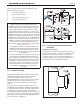
NOTE: This unit and all other gas appliances sharing
the gas supply line must be ring at maximum
capacity to properly measure the inlet supply
pressure. The pressure can be measured at the
supply pressure port on the gas valve. Low gas
pressure could be an indication of an undersized
gas meter, undersized gas supply lines and/or an
obstructed gas supply line. Some Units are equipped
with low and high pressure gas switches that are
integrally vent limited. These types of devices do not
require venting to atmosphere.