
Install Instructions


LAARS Heating Systems
SECTION 1
GENERAL INFORMATION
1.A Introduction ....................................................... 1
1.B Warranty ........................................................... 1
1.C Model Identication ........................................... 1
1.D Safety Notes ..................................................... 2
1.E Model Overview ................................................ 4
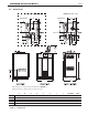
1.F Dimensions ....................................................... 5
1.G The Installation Kit ............................................ 6
SECTION 2
LOCATING THE UNIT
2.A General Information .......................................... 7
2.B Locating Unit for Correct Vent Distance
from Outside Wall or Roof Termination ............. 7
SECTION 3
VENTING AND COMBUSTION AIR
3.A General Venting ................................................ 8
3.B Combustion Air ................................................. 8
3.C Venting ............................................................ 10
3.D Common Venting ............................................ 11
3.E Locating Vent & Combustion Air Terminals ..... 11
3.F Common Vent Test ......................................... 15
SECTION 4
GAS SUPPLY AND PIPING
4.A Gas Supply and Piping ................................... 15
SECTION 5
PUMP REQUIREMENTS
5.A Boiler Flow and
Head Requirements ........................................ 16
SECTION 6
WATER CONNECTIONS
6.A System Piping - Hot Supply
Connections .................................................... 17
6.B Cold Water Make-Up ...................................... 17
6.C Condensate Drain ........................................... 18
6.D Freeze Protection ........................................... 18
6.E Recognized Chemicals ................................... 18
6.F Suggested Piping Schematics .................19 - 25
SECTION 7
ELECTRICAL AND WIRING DIAGRAMS
7.A Installation Warnings ...................................... 26
7.B Main Power Connections ................................ 26
7.C Pump Connections and Operation ................. 26
7.D Hydronic Heating Using External Mod ............ 27
7.E Optional Field Connections ............................. 27
7.F Lead Lag Connections .................................... 28
7.G System Wiring Diagram .................................. 30
7.H Ladder Diagram .............................................. 32
SECTION 8
THE USER INTERFACE
8.A About the User Interface ................................. 33
8.B Navigating the User Interface ......................... 33
8.C The Home Display .......................................... 34
8.D Customizing your Home Display .................... 34
8.E Entering / Changing Control Settings
(including PASSWORDS) ........34 - 36
8.F Quick Start Menu ............................................37
Conguration and Setup
8.G 24 VAC Transformer with Integral
Circuit Breaker ................................................ 38
8.H Hydronic Heating Demand ............................. 38
8.I Anti-Short-Cycle ............................................. 38
8.J Outdoor Air Temperature Sensor .................... 38
8.K Outdoor Reset ................................................ 39
8.L Warm Weather Shutdown ............................... 40
8.M Domestic Hot Water........................................ 41
8.N About Lead Lag Operation ............................. 43
8.O Adjusting CO
2
................................................ 46
Table of Contents
i