
Install Instructions

Page 11
NEOTHERM Residential Boilers
HIGH EFFICIENCY RESIDENTIAL BOILERS
®
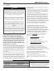
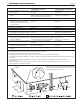
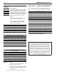
Figure 5. - Test Port - ULC-S636 system
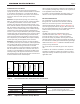
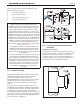
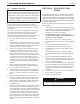
Figure 4. - Combustion Air and Vent Through Roof
*
*
*
*
*
*
*
In Canada, refer to CAN/CSA B149.1
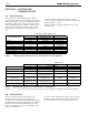
Class II venting systems are further classied into four
temperature ratings as follows:
A Up to and including 65°C
B Up to and including 90°C
C Up to and including 110°C, and
D Up to and including 135°C
NOTE: IMPORTANT! It is the responsibility of the
installer to ensure that a ue gas sampling port is
installed in the vent system. This ue gas sampling port
must be installed near the ue connection of the unit:
within 2 feet of the ue connection. There is no ue
gas sampling port internal to the unit, so one must be
installed in the vent system external to the unit. A ue gas
sampling port available as a component of the ULC S636
certied vent system is preferred. However, if one is not
available with the certied vent system, the Manufacturer
suggests using a tee with the branch connection sized
to allow for insertion of a ue gas analyzer probe. The
branch connection must be resealable with a cap or
other by other means to ensure the vent system remains
sealed. (See Figure 5.)
Consideration must be given to the placement and
orientation of the ue gas sampling port to ensure that
condensate is free to ow back into the Unit and not
collect anywhere in the vent system - including in the ue
gas sampling port.
An exhaust vent terminal must be installed. If an exhaust
vent terminal is not available with the certied vent
system, the Manufacturer suggests the use of a coupler
tting from the certied vent system into which the vent
terminal screen, included with the unit and shown in
the Unpacking section, be installed. Be sure to install
and terminate both vent and combustion air pipes per
the Venting and Combustion Air section of the unit
instructions.
3.D Common Venting
High eciency boilers and water heaters may be common
vented using Non-Return Valve kits and Centrotherm
InnoFlue polypropylene venting. Go online to
www.BradfordWhite.com and refer to the Common Venting
Installation Instructions, document number 1427, for
instructions on sizing and installing a common venting
system.
If common venting is required on larger model sizes or
with dierent venting materials, it MUST be engineered by
a competent venting specialist, and involves the selection
of draft inducing equipment, hardware and controls to
properly balance ue gas pressures. Do not common vent
these units unless the vent system meets this requirement.
High eciency class IV units are never permitted to share
a vent with Category I appliances.
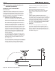
3.E Locating Vent and Combustion Air
Terminals
Side Wall Vent Terminal
The appropriate side wall vent terminal must be used. The
terminal must be located in accordance with ANSI Z223.1/
NFPA 54 and applicable local codes. In Canada, the
installation must be in accordance with CSA B149.1 or .2
and local applicable codes. Consider the points listed on
the following page when installing the terminal.