
Install Instructions

Page 9
NEOTHERM Residential Boilers
HIGH EFFICIENCY RESIDENTIAL BOILERS
®
Other methods of introducing combustion and ventilation air
are acceptable, providing they conform to the requirements
in the applicable codes listed above.
In Canada, consult local building and safety codes or, in
absence of such requirements, follow CAN/CSA B149.
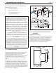
Ducted Combustion Air
The combustion air can be taken through the wall, or
through the roof. When taken from the wall, it must be
taken from out-of-doors by means of the Manufacturer
horizontal wall terminal, shown in Table 6. See Table 3 to
select the appropriate diameter air pipe. When taken from
the roof, a eld-supplied rain cap or an elbow arrangement
must be used to prevent entry of rain water. (See
Figure10.)
Use ABS, PVC, CPVC or galvanized pipe for the
combustion air intake. (See Table 7) The pipe should
be sized per Table 3 on page 7. Route the intake to
the boiler as directly as possible. Seal all joints. Provide
adequate hangers. The unit must not support the weight of
the combustion air intake pipe. Maximum linear pipe length
allowed is shown in Table 3. Subtract 5 allowable linear ft.
(1.5m) for every elbow used.
The connection for the intake air pipe is at the top of the
unit.
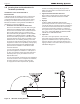
In addition to air needed for combustion, air shall also be
supplied for ventilation, including air required for comfort
and proper working conditions for personnel. Refer to the
applicable codes.
Combustion Air From Room
In the United States, the most common requirements
specify that the space shall communicate with the outdoors
in accordance with method 1 or 2, which follow. Where
ducts are used, they shall be of the same cross-sectional
area as the free area of the openings to which they
connect.
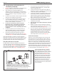
Method 1: Two permanent openings, one commencing
within 12” (300mm) of the top and one commencing within
12” (300mm) of the bottom, of the enclosure shall be
provided. The openings shall communicate directly, or by
ducts, with the outdoors or spaces that freely communicate
with the outdoors. When directly communicating with the
outdoors, or when communicating to the outdoors through
vertical ducts, each opening shall have a minimum free
area of 1 square inch per 4000 Btu/hr (550 square mm/kW)
of total input rating of all equipment in the enclosure. When
communicating to the outdoors through horizontal ducts,
each opening shall have a minimum free area of not less
than 1 square inch per 2000 Btu/hr (1100 square mm/kW)
of total input rating of all equipment in the enclosure.
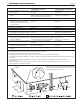
Method 2: One permanent opening, commencing within
12” (300mm) of the top of the enclosure, shall be permitted.
The opening shall directly communicate with the outdoors
or shall communicate through a vertical or horizontal
duct to the outdoors or spaces that directly communicate
with the outdoors and shall have a minimum free area of
1 square inch per 3000 Btu/hr (734 square mm/kW) of the
total input rating of all equipment located in the enclosure.
This opening must not be less than the sum of the areas of
all vent connectors in the conned space.
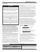
INSTALLATION STANDARDS
MATERIAL UNITED STATES CANADA
ABS ANSI/ASTM D1527
PVC, sch 40 ANSI/ASTM D1785 or D2665 Air pipe material must be chosen
CPVC, sch 40 ANSI/ASTM F441
based upon the intended application of the boiler.
Single wall galv. steel 26 gauge
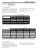
HORIZONTAL INTAKE AND EXHAUST PVC VENT TERMINAL KITS
Size
2” PVC
3” PVC
4” PVC
6” PVC
Standard
Concentric
CA006000
Flush Mount
CA010100
Standard
CA005900
Concentric
239-44069-01
Flush Mount
CA010101
Standard
Flush Mount
CA010102
Standard
80
incl.
opt.
opt.
opt.
opt.
opt.
n/a
n/a
n/a
105
incl.
opt.
opt.
opt.
opt.
opt.l
n/a
n/a
n/a
150
n/a
n/a
n/a
incl.
opt.
opt.
n/a
n/a
n/a
199/210
n/a
n/a
n/a
incl.
opt.
opt.
n/a
n/a
n/a
285
n/a
n/a
n/a
opt.
opt.
opt.
incl.
opt.
n/a
399
n/a
n/a
n/a
n/a
n/a
n/a
incl.
opt.
n/a
500
n/a
n/a
n/a
n/a
n/a
n/a
incl.
opt.
n/a
600
n/a
n/a
n/a
n/a
n/a
n/a
incl.
opt.
opt.
750
n/a
n/a
n/a
n/a
n/a
n/a
incl.
n/a
opt.
850
n/a
n/a
n/a
n/a
n/a
n/a
incl.
n/a
opt.
Concentric vent terminal = 10 ft. pipe length
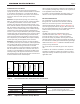
Table 6. - PVC Horizontal Intake and Exhaust Vent Terminal Kits
Table 7. - Required Combustion Air Pipe Material