
User Guide


67
Service Manual NeoTherm 80 - NeoTherm 285
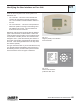
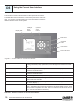
Setup Mode
TogototheSetupMode,pressandholdtheUpand
Downbuttonsatthesametimeforaboutthreeseconds.
Theinterfacewillindicate“°F.”
PressNexttogotothesetupforOutdoorReset(shown
as“LBTHODLOD”).UsetheUpbuttontoturnonthe
OutdoorResetfeature,ifdesired.Oncethisisenabled,
pressNexttogotothelinesforLowBoilerSetpoint
(LBT),HighOutdoorTemperature(HOD),andLowOut-
doorTemperature(LOD).Tochangeanyofthese,use
theUpandDownbuttons.(Youdonotneedtopress
Doneyet.)
UsetheNextbuttontostepthroughtheotheritemsin
thismenu.Toseethecurrentsetpointforanitem,press
theUpbutton.ThenusetheUpandDownbuttonsto
change the setpoint.
Important-WhenyouwanttoleavetheSetupMode,
presstheDonebuttontosaveanychangesyouhave
made.Ifyoudonotdothis,thesystemwillusetheold
setpoints.
MENUITEM DEFINITION
ForC Selectstemperatureunits
LBTHODLOD Outdoorresetenable/disable-
enablesfollowingmenuitems
LBT Lowboilersetpointduringoutdoorreset
HOD Highoutdoortemperaturesetpoint
LOD Lowoutdoortemperaturesetpoint
RMTAdd Remoteaddress-usedforLead/Lagsetup
LL Lead/Lagenable/disable-enablesmenuitems
HS Hysteresis-temprangebetweenon/offcycles
bL BaseLoad%-inputratebeforenextboilerres
Sd Warmweathershut-downtemperature
ASC Antishortcycle-minutesofdelaybetween
startups
Table D2-2 - Setup Mode Parameters
Using the Original (White) User Interface - continued
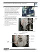
Diagnostic Mode
DiagnosticModeallowsyoutoseeanyalertsorlock-
outs.Thismodeisalsousedtosetupthe“highre”and
“lowre”conditionssoyoucandothegasvalve/CO
2
adjustment.
TogototheDiagnosticMode,pressandholdtheNext
buttonforthreeseconds.Thedisplaywillindicatea
value,followedby“µA.”Thisisthesignalfromtheame
sensor.
PressNextagaintoseethelastalert(sincetheunit
waslastturnedon),andpressNextagaintoseethe
lastlockout.(Thereisalistofthelockoutcodesinthe
Appendixattheendofthismanual.)Thetablebelow
showstheotherfunctionsintheDiagnosticMode.Use
theNextbuttontostepthroughthesefunctions.
Tosetupthegasvalve,pressNextuntilthedisplaysays
“Min.”WhenyoupressNextagain,thedisplaywillstep
betweenanumber(thecurrentoutlettemperature)and
“10%”(thecurrentringrate).Atthispointthecontroller
isreadytodothe“lowre”setup.
MENUITEM DESCRIPTION
µA Displaystheamesensesignal
Alertcodes Displaysthecurrentalertcode
Lockoutcode Displaysthecurrentlockoutcode
OutletLimit Displaystheoutlettemperaturelimit
DHWlimit DisplaystheDomesticHotWaterlimit
setting
StackLimit DisplaystheStacklimitsetting
Min.ringrate Displaystheminimumringrateallowed
Min.forced Allowstheusertoforcetheboilertoreat
ringrate theminimumringrate
Maxforced Allowstheusertoforcetheboilertoreat
ringrate themaximumringrate
Rateindicator Displaysthecurrentringratebased
onthefanRPM.
Table D2-3 - Diagnostic Mode Menu Structure
D2
cont.