Document 1291 Service Manual for NEOTHERM Modulating Boiler Model NTH Sizes 080–285 MBTU/h Water Heater Model NTV Sizes 150–285 MBTU/h Every reference that you’ll need, to service the Residential NEOTHERM ®
How to Use This Manual How to Use the Troubleshooting Information This manual is divided into five main sections: Section A - Troubleshooting Instructions Section B - Troubleshooting Procedures Section C - Combustion Section D - NeoTherm Control System Appendix Start the troubleshooting process using the charts in Section A. The instructions in Section A will lead you to more detailed procedures in Section B.
Finding Information in this PDF File This manual includes a lot of detailed information, but none of this is very useful to you unless you can find it. We’d like to help you to find the information you need, quickly and easily. There are four ways to locate information in this PDF* file. Bookmarks When you first open this file on your computer, it will display a list of “Bookmarks” along the left edge of the page. Scroll down the list until you see the item you want.
Safety Notes Please read this section before beginning any troubleshooting procedures. DANGER If the information in this manual is not followed exactly, a fire or explosion may result, causing loss of life, personal injury, or property damage. Necessary Training This product must be installed and serviced by a professional service technician, qualified and/or licensed in hot water boiler and heater installation and maintenance.
Electrical Shock Hazard Electrical shock can cause severe injury, death or property damage. Only a professional technician, trained in electrical safety, should work on this unit. Whenever the troubleshooting procedures make this possible, turn off the power to the unit before working inside the cabinet. The only exceptions would be when it is necessary to test the voltages between the points listed in this manual. 120V AC is present in this unit behind the metal cover marked with the safety label.
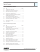
Table of Contents Section A - Troubleshooting - Start Here Sect. Title.................................................................................Page A1 Troubleshooting - Start Here................................................ 1 A2 Unit Will Not Fire - Blower is Not Running............................ 2 A3 Blower Runs Continuously, No Display................................ 4 A4 Control Unit is in “Standby” Mode.........................................
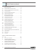
Table of Contents (continued) B15 Checking the Air Pressure Switch Blower Proving Switch........................................................ 33 B16 Test Procedure for Air Pressure Switch.............................. 34 B17 Removing and Replacing the Air Pressure Switch............. 34 B18 Checking the Blower........................................................... 36 B19 Removing and Replacing the Blower................................. 37 B20 High Stack Temperature Fault..........
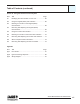
Table of Contents (continued) Section D - Using the NeoTherm Control System Sect. Title Page D1 Identifying the User Interface on Your Unit......................... 65 D2 Using the Original (White) User Interface........................... 66 D3 Reacting to Lockouts on the Original (White) User Interface..................................................................... 68 D4 Removing and Replacing the Original (White) User Interface.......................................................
viii Service Manual NeoTherm 80 - NeoTherm 285
A1 Troubleshooting - Start Here Is this a new installation? Did the unit ever run correctly? New installation, never ran correctly See “Quick Check of Components in the Safety Chain and Firing Sequence” - Section B1 Old installation, ran correctly What changed? Operating conditions? Did you change any control settings? For troubleshooting instructions, see these sections: Section Symptom Page A2 Unit Will Not Fire, Blower is Not Running 2 A3 Blower Runs Continuously, No Display 4 A4 Co
A2 Unit Will Not Fire - Blower is Not Running Display is lit? No Check 120V AC electrical power. See Section B2 “Troubleshooting the 24V AC Power Supply” Yes Has call for heat? No Yes Blower-related problem? Short contacts: Central Heat: 5-7 on TB7 DHW: 5-6 on TB6 Original user interface shows: Check, Pre-Purge, Run = Normal operation Current user interface shows: Heat demand or DHW = Normal operation Check for correct “call for heat” signal.
A2 Unit Will Not Fire - Blower is Not Running Incoming gas pressure is OK? No cont. Adjust regulator. Check with gas company. Yes Problem indication from controller? Yes - Code number supplied See table of code numbers in Appendix. Yes See Section A4 “Control Unit is in Standby Mode” No Controller stuck in Standby mode? No Check programming in controller temperature settings, outdoor reset, etc. Settings OK? No Correct the settings. Yes Replace the SOLA controller.
A3 Blower Runs Continuously, No Display In this condition, the blower is running continuously, but the display is completely blank. Reset 24V breaker switch under transformer. Resets? Yes No Check the 24V power supply. See Section B2.
A4 Control Unit is in “Standby” Mode In certain situations, the controller on this unit can go into “Standby” mode. The Boiler pump is running, so the unit sees a “Call for heat.” There is no lockout or hold, but something is preventing it from going to “Run” mode. Normal operating condition? Yes No Check for: - Call for heat? - System is up to set-point temp. - no need for more heat? - If warm weather shutdown is enabled: Outdoor air temperature too warm? Disconnect outdoor temp.
A4 cont. Control Unit is in “Standby” Mode (continued) Example: High flue temperature trips High Stack Temp. Sensor. Unit will not run for 20 min., then automatically resets.
Changing Control Settings, Change Not Complete Original (White) Interface A5 NeoTherm units were produced using two types of user interfaces. (See Section A1 to identify the kind of interface used on your unit.) These instructions apply to units with the original (white) user interface. In certain situations, the controller used in this unit can go into a “Standby” mode. There is no lockout or hold, but the unit still will not run.
A6 Unit is Running, But Building is Still Cold Air inlet is blocked? Yes Clear it Yes Clean Yes Clean, blow out No Air intake inside unit is plugged? No Dirty fan? No Burner and/or heat exchanger plugged? Yes See “Cleaning the Burner and Heat Exchanger” Section C5 8 Service Manual NeoTherm 80 - NeoTherm 285 (Gas/air mixture is correct, but not enough gas/air mixture is supplied.
Control Unit Says “Run,” But Boiler is Not Firing A7 In this condition, the panel is lighted, so you know the unit has power. The Boiler pump is running, so you know the unit is receiving the call for heat. The blower is running, the unit has spark, and the gas valve is operating correctly. Unit is operating correctly - recovering from a trouble condition? No Example: Stack temp. limit trips, automatically resets after 20 minutes. Until this happens, the display says “Run” but the unit will not fire.
A9 Short-Cycling - Fault #61 There are several conditions that can cause short-cycling, and some of them can be caused by problems with the installation. Start by checking the control settings for On Hysteresis and Off Hysteresis. If these are set too low, the system can short-cycle. Short-cycling can occur if the piping in the hydronic loop is too small for the capacity of the boiler.
B1 Quick Check of Components in the Safety Interlock Chain This procedure gives you a quick way of checking the safety switches and some of the control functions in the unit. This will allow you to rule out some large sections of the control system, and find the part of the system that actually has the problem. DANGER! - When the cover is opened, some of the areas carrying 120V AC voltage will not be covered. Do not perform the following tests unless you have been trained how to do this safely by Laars. 1.
B1 cont. Quick Check of Components in the Safety Interlock Chain - continued 6. If this unit is set up to use a separate DHW signal – Insert a jumper across terminals 5 and 6 on TB-6 on the control board. See Fig. B1-3. This will create a permanent “Call for DHW” signal. (Again, remember to remove this when you are through.) BOILER PUMP SYSTEM PUMP DHW PUMP 7. Turn on power to the unit. 8. Check for 24V AC between terminal blocks TB-3 and TB-4. See Fig. B1-4.
B1 Quick Check of Components in the Safety Interlock Chain - continued cont. 10. Check for 24V AC between terminals 1 and 2 of J8 on the control module. See Fig. B1-6. If 24V AC is present here, this means that the Condensate trap level switch is OK. If 24V AC is not present, troubleshoot the condensate trap level switch. See Section B12. 11. If you see 24V AC at J8, this means that all of the switches in the safety chain are satisfied.
B1 cont. Quick Check of Components in the Safety Interlock Chain - continued 12. If the unit is receiving a “call for heat,” and all of the safety switches are OK, the blower should be receiving control voltage through J2 on the control module. See Fig. B1-8. • If power is available at J2, but the blower is not running, go to Section B18 - “Checking the Blower.” • If the blower is running, and the unit does not fire, go to Section B28 - “Testing the Temperature Sensors.” 13.
B2 Troubleshooting the 24V AC Power Supply 24V AC between TB3 and TB4? Yes 24V AC supply is OK No Reset circuit bkr. on transformer 24V OK now? Yes 24V AC supply is OK Why did breaker trip? Loose or damaged wire? No Disconnect power. Check for continuity through primary and secondary windings of transformer. Check for short to frame from primary and secondary windings of transformer. Replace if necessary. Check for bad transformer Trans.
B3 Checking the Safety Interlocks Check for 24V AC between TB8-1 and TB4-1. 24V AC is present? (all switches closed) Yes Safety interlock chain is OK No Check for 24V AC between TB8-2 and TB4-1. 24V AC is present? Yes See procedure B4 “Checking the Low Water Cutoff Switch” No Check for 24V AC between TB8-4 and TB4-1. 24V AC is present? Yes No Check the optional external high limit switch: 1. Check for actual high outlet temp. condition (manual reset) 2. Check temp. setting on switch 3.
B3 Checking the Safety Interlocks - continued cont. Check for 24V AC at terminal J6-1. 24V AC is present? (other safety switches closed) No See procedure B12 “Checking Condensate Trap Level Switch” Yes With boiler attempting to run, check for 24V AC across two leads on air pressure switch. 24V AC is present? (switch open) Yes See procedure B15 “Checking the Air Pressure Switch” No NT unit should be trying to fire. If not firing, control panel should be displaying an error code.
B4 Checking the Low Water Cutoff Switch (option) Check for water in boiler? Water present? No Check water supply, water pressure, and auto makeup valve. Yes OK - temporary condition Yes Reset low water cutoff control Control resets? No Are you using ultra-pure water? Ultra-pure water? Yes Ultra-pure water will not conduct electrical current = false low water reading No Check for continuity from base of switch to ground.
Checking the Low Water Cutoff Switch (continued) B4 cont. Check for dirty probe. Probe dirty? No The system may have tripped because of small air bubbles. Yes Drain and flush the system. Yes Wipe down the probe. (Do this once a year.) System recently installed? B5 Controller for Low Water Cutoff The low water cutoff switch operates by passing a slight electrical current between from a probe to ground when water is surrounding the probe.
B6 Removing and Replacing the Low Water Cutoff Switch The low water cutoff switch is designed to shut down the unit if there is a low water condition. The control includes two parts: a control box, and a probe which reaches into the water piping. You may need to unscrew these screws to allow clearance for the wrenches behind the probe assembly.
Removing and Replacing the Low Water Cutoff Switch (continued) Procedure - Replacing the control box 3. The control box is attached to the backing plate by two sheet-metal screws with large heads. See Fig. B6-4. One of these holds the green ground wire. Use the 5/16” socket to loosen both of these. Remove the green ground wire from the left-hand screw. Twist the box slightly and pull it away from the backing plate. 4. To reassemble, reverse the procedure we have just described.
B7 High Water Temperature Limit Switch (optional) Laars does not provide this switch. It is installed only where required. This is a normally-closed (NC) switch. If the water temperature rises above the pre-set limit, the switch opens. Some types of switches must be reset manually. To reset this type of switch, press the button on the control. Other switches will reset automatically. Correct the cause of the problem and/or replace the switch.
B9 Testing the Flow Switch The flow switch uses a set of paddles to sense water flowing through the system. See Fig. B9-1. When water is flowing, the switch is normally closed (N.C.). If the water flow stops, the switch opens. After a “no flow” condition, the switch resets itself immediately and automatically. Use a volt-ohmmeter to test the continuity through the switch. With the paddles in the “relaxed” position (standing upright), the switch should be open.
B10 Removing and Replacing the Flow Switch The switch assembly includes two parts: a set of paddles that extend into the water pipe, and a control box. See Fig. B10-1. Figure B10-2 shows the paddles that extend into the piping to detect the water flow. The paddles are sized to match the amount of water flowing through the system, so a flow switch installed in a smaller system, with a smaller pipe, will have smaller paddles, and a switch in a larger system will have larger paddles.
Removing and Replacing the Flow Switch (continued) B10 cont. 5. Now you can use the pipe wrench to remove the whole switch assembly. 6. When you receive the new switch, it will include four paddles. These will be longer than necessary for your installation, so you will need to trim these paddles to the correct sizes. The best way to do this is to copy the sizes of the paddles in the old switch. Make a smooth curve at the end of each paddle, as shown in the photo.
B11 Removing and Replacing the Gas Valve The modulating gas valve consists of a valve body that controls the on/off gas flow and a negative pressure regulator. It provides the air/gas ratio control in combination with the Venturi to the unit. The easiest way to remove the gas valve is to remove the air/gas channel and blower as one assembly, then separate the gas valve from the assembly.
B11 Removing and Replacing the Gas Valve (continued) cont. 4. Unplug the wires running to the gas valve. The connector is keyed, and can only be plugged in one way. See Fig. B11-3. 5. Disconnect the small vacuum hose running to the top of the gas valve. 6. Disconnect the wires to the blower. There are two connectors. The power wires run to the rear connector, and the control wires connect to the front. See Fig. B11-4. 7.
B11 cont. Removing and Replacing the Gas Valve (continued) 8. The gas inlet pipe runs to the underside of the gas valve. It is attached by four 3mm Allen-head screws, and these are difficult to reach. Figure B11-6 shows the screws as seen from below the gas valve. Use a 3mm Allen wrench to undo these screws. It will be hard to reach one of the screws. The best tool for this job is a traditional “L-shaped” Allen wrench, with one long leg and one short leg.
Removing and Replacing the Gas Valve (continued) 11. Now you can remove the gas valve. There are four 4mm socket-head cap screws. Fig. B11-9 shows the gas valve once it has been removed. Here are two points to keep in mind: • Notice the rubber washer. Be sure to insert this in the correct position when installing the new valve. 13. After reassembly, check for gas leaks using a leak detection solution. cont. Rubber washer On/Off switch • The gas valve has an On/Off switch. See Fig. B11-10.
B12 Checking the Condensate Trap Level Switch Check for 24V AC across switch. 24V AC present? (switch open) No See Section B3 “Checking the Safety Interlocks” Yes Check for blocked or frozen condensate outlet. Outlet blocked? No Yes Flush outlet with water. 30 Service Manual NeoTherm 80 - NeoTherm 285 Test switch, replace if necessary. See the test procedure Section B13.
B13 Testing the Condensate Trap Level Switch Some operating conditions can cause small particles of mineral material to be formed in the heat exchanger and collect in the condensate trap. The drain can also be blocked if it is frozen or plugged with debris. If the water cannot drain freely, it can back up into the heat exchanger. The level switch is designed to prevent this by shutting off the unit before the water can reach the heat exchanger. Setscrew This assembly uses a float-type switch.
B14 cont. Removing and Replacing the Condensate Trap (continued) Tools and equipment required: * 1/4” socket • Small diagonal cutters or knife • Water-pump pliers • 11” Ty-wrap Procedure 1. Turn off power to the system. Use the main disconnect switch mounted above the front panel. 2. Remove the front panel from the unit. 3. You won’t be able to do this procedure unless you also remove the panel on the right side of the unit. Remove the mounting screws, then remove the right side panel. 4.
Checking the Air Pressure Switch - Blower Proving Switch B15 Check for blocked air intake and exhaust vents. Exhaust vent blocked? Yes Clear the vents. Check the bird screens or terminals. No Dirty fan? Yes Clean with a shop-vac. No Test the air pressure switch. (See Section B16.) Switch is OK? No Replace switch. Yes See Section B18 “Checking the Blower” Yes Problem with blower? No Heat exchanger is plugged? Yes Clean the heat exchanger. See Section C5.
B16 Test Procedure for Air Pressure Switch 1. The switch is located behind the front panel. Disconnect the two leads, and connect a Volt-Ohmmeter set to check for continuity (reading Ohms). 2. Insert a hose “T” in the clear plastic hose that runs to the positive pressure port (closest to the electrical connections). Attach a length of hose to the branch of the “T.” 3. Blow on the end of the hose.
Removing and Replacing the Air Pressure Switch (continued) B17 cont. Procedure - Removing or replacing the switch 1. Turn off power to the machine. Use the main disconnect switch located above the top of the control panel. 2. Remove the covers on top of the unit so you can reach the air pressure switch. 3. Remove the mounting screws on both sides of the switch. Use the screwdriver or the 5/16” socket. 4. Use the pliers to release the hose clamps and remove the air hoses from the bottom of the switch.
B18 Checking the Blower At start of test, unit should be ready to run (”Standby”) Has call for heat? No Short contacts for call for heat: CH: TB7 5-6 DHW: TB6 5-6 Blower runs Problem with temp. sensor(s) System sensor - Section B22 DHW sensor - Section B23 Blower does not run Unplug J2. This is the control signal to the blower. Blower goes to full speed? No Bad blower. Replace the blower. See Section B19. No Replace wire harness Yes Check wiring harness.
B19 Removing and Replacing the Blower The easiest way to remove the blower is to remove the air/gas channel and blower as an assembly, then separate the blower from the assembly. Because of the way the blower is mounted in the machine, it would be very difficult to remove the blower from the machine directly. Figure B19-1 shows how the parts are arranged.
B19 cont. Removing and Replacing the Blower (continued) 4. Unplug the wires running to the gas valve. The connector is keyed, and can only be plugged in one way. See Fig. B19-3. 5. Disconnect the small vacuum hose running to the top of the gas valve. 6. Disconnect the wires to the blower. There are two connectors. The power wires run to the rear connector, and the control wires connect to the front. See Fig. B19-4. 7.
B19 Removing and Replacing the Blower (continued) cont. 9. Now you can remove the air/gas channel and blower assembly from the machine. See Fig. B197. Remove the five #25 Torx-head screws around the air/gas channel assembly. (These are the outer screws on the front of the assembly. The inner screws attach the air/ gas channel cover - do not remove these.) Remove these screws Support the assembly as you remove the last screws, so it does not fall.
B20 High Stack Temperature Fault Actual stack temperature problem? Yes Correct this immediately. Blocked exhaust outlet? Dirty heat exchanger? If you have the current user interface, set the stack temperature limit to 190°F. Yes See Section B34 No Check the continuity on the wires from the sensor to J9-4, J9-5, and J9-6 on the control module. No Problem with circulator pump? No Wiring to sensor is correct? Good connections? Yes Replace the sensor.
Removing and Replacing the Stack Temperature Limit Switch B21 The stack temperature limit switch will shut down the NT unit if the stack temperature rises above 195°F. This is a “duplex” sensor - it actually includes two separate thermistors. The control system constantly compares the readings from the thermistors. If there is a large difference between the readings, or if one of the thermistors is “open” or “shorted,” the control system will shut down the NT unit, and display a “Hold 95” error message.
B22 Checking the System Sensor The System sensor is mounted in the circulating loop, and provides the input for the CH (Central Heating) function. This type of sensor can fail in either an “open” or “shorted” condition, or may become inaccurate. On a unit with the current user interface Check the line on the display for “LL OPER TEMP.” If the sensor is operating normally, the unit will display a temperature on this line.
B24 Inlet Water Temperature Sensor A typical installation for the inlet water temperature sensor is shown in Fig. B24-1. The sensor is connected to J8 4-5 on the control module. This sensor uses an electronic device called a “thermistor.” For instructions on testing the sensor, see Section B28. Sensor To reset the control system after the inlet sensor trips: • On a unit with the original (white) user interface - Press the Reset button near the lower left-hand corner of the display.
B26 Outlet Water Temperature Sensor The outlet water temperature switch allows the control system to monitor the temperature of the water as it leaves the NT unit. A typical installation for the outlet water temperature sensor is shown in Fig. B26-1. The sensor is connected to J8 8-9-10 on the control module. Sensor This sensor assembly includes two electronic devices called “thermistors.” As long as the resistance readings from both sensors agree, the NeoTherm will continue to operate.
Removing and Replacing the Outlet Water Temperature Sensor (continued) B27 cont. 4. The outlet water temperature sensor is mounted in the shoulder of the heat exchanger assembly, just above the point where the water outlet pipe is attached to the heat exchanger. (The outlet pipe is marked with a label on top of the unit.) Remove the top panels on the unit so you can reach the temperature sensor. 5. Unplug the wiring connector (four wires). The connector is locked in place by a “squeeze tab.
B29 Troubleshooting the Outdoor Reset System Disconnect 1 lead from outdoor temperature sensor Unit starts running? Yes Reconnect the sensor lead Is Outdoor Reset enabled on the controller? Check programming Example - Low boiler temp. set to 130°, heat setpoint set to 120°, so unit never fires. Example - High and low boiler temps. set the same, so unit never fires. The high temp. setting must always be higher than the low temp. setting.
B30 Servicing the Transformer (continued) cont. Tools and equipment required: • Volt-Ohmmeter • Phillips head screwdriver (size #1) • Deep socket for transformer mounting nuts Test Procedure: It is simplest to test the transformer by checking the voltages at other points on the NT unit. Reset switch 1. Turn on power to the unit. Warning! You will be working with sections of the machine that will carry 120V AC.
B31 Removing and Replacing the Pressure Relief Valve Note Normally a drain pipe would run from here to within 6” of the floor. If the system pressure exceeds the relief valve setting, the pressure relief valve is designed to open and release the excess pressure and water. Note - This type of valve is designed to relieve a limited number of times during its life cycle, so it is not a good idea to “test” the valve by tripping the small metal handle on top.
B32 Ignitor Assembly The ignitor assembly is a two-rod system that consists of a ground rod and a spark rod. Adjustment Procedure: 1. Shut off the 120V power supply to the unit. 2. Turn off all manual gas valves connecting the unit to the main gas supply line. 3. Remove the front door of the unit to gain access to the ignitor assembly. 4. The end of each spark rod should be at least 1/4” away from the burner. 5. Set the gap between the spark rods at 3/16” ± 1/16.
B33 Flame Sensor The flame sensor is a single-rod system, and is mounted in the front cover of the heat exchanger. Over time, this sensor can become tarnished or coated. (This will happen more quickly if the NT unit has been operating often at a low firing rate.) The flame sensor has a protective coating. Important! Do not use sandpaper, steel wool, or emery board to clean the flame sensor. These materials will clean the sensor, but they will also remove the protective coating.
B34 Pump Fault A problem with the circulator pump could appear as a #79 error (Outlet High Limit). It could also appear as a #63 error (LCI - Limit Control Input) if the interlock loop includes a flow switch. The SOLA controller also can display error #51 - Pump Fault. Pump is getting power? No Check for 120V at terminals 1 and 2 on TB5.
52 Service Manual NeoTherm 80 - NeoTherm 285
C1 Possible Combustion Problems About Correct Combustion When the unit is firing, the gas valve must always supply the correct amount of gas to match the amount of air going through the burner. The ratio of gas to air remains constant, but the control module adjusts the blower speed to adjust for changes in heat load.
C2 Combustion Adjustment Procedure Units with Original (White) User Interface WARNING Improper adjustment may lead to poor combustion quality, increasing the amount of carbon monoxide produced. Excessive carbon monoxide levels may lead to personal injury or death. Equipment required: • Combustion analyzer • 2 mm Allen wrench Procedure: 1. Measure the CO2 and O2 in the flue products at High Fire. The NeoTherm must be forced go to High Fire to obtain accurate results.
Combustion Adjustment Procedure Units with Original (White) User Interface - continued C2 cont. 2. Once you have completed the high fire combustion test, measure the CO2/ O2 in the flue products at Low Fire. How to get there: Use the Down arrow to set the “Rate” to “20%.” The NT unit is now forced to low fire mode for 5 minutes. The CO2 readings should be between the values shown in Table C2-1. If the CO2 is not within the range shown, adjustments may be made.
C3 Combustion Adjustment Procedure Units with Current User Interface WARNING Improper adjustment of the high fire and low fire settings may lead to poor combustion, increasing the amount of carbon monoxide produced. Excessive carbon monoxide levels may lead to personal injury or death. Equipment required: • Flue product analyzer • 2 mm Allen wrench Procedure: 1. Start by measuring the CO2 and O2 in the flue products at high fire.
C3 Combustion Adjustment Procedure Units with Current User Interface (continued) cont. 2. Next, measure the CO2 and O2 in the flue products at low fire. The NeoTherm can be forced to remain in low fire during the setup. How to get there: From the “Home” screen, press “I” to go to “Info/ Install.” Choose “Test,” then go to “Forced Rate.” Select “Set Low Fire,” then select “Start Test.” Again, the CO2 readings should be between the values shown in Table C3-1. See Fig.
C4 Troubleshooting Combustion Problems During adjiustment, can reach target figures in Table? Can reach Combustion is OK. No Gas supply problem. Check with gas company. Yes Check all hoses, tighten all connections. No Clean burner and heat exchanger. See Section C5. Cannot reach Gas inlet pressure OK? Yes Any gas leaks inside the unit? No Interior of burner is clean? Replace gas valve.
C5 Cleaning the Burner and Heat Exchanger The buildup of black carbon soot on the external surfaces of the heat exchanger can be caused by one or more of the following: incomplete combustion, combustion air problems, venting problems, and shortcycling. Soot buildup or other debris on the heat exchanger may restrict the flue passages. Laars recommends the unit be inspected once a year, and cleaned if necessary.
C5 cont. Cleaning the Burner and Heat Exchanger (continued) Disassembly Procedure: 1. Turn off power to the machine. Use the main disconnect switch on the front of the machine, just above the control panel. 2. Remove the front panel. 3. Shut off the gas at the gas shutoff valve on the right side of the machine (yellow handle). 4. Unplug the wires running to the gas valve. The connector is keyed, and can only be plugged in one way. 5.
C5 Cleaning the Burner and Heat Exchanger (continued) cont. 8. The gas inlet pipe (black pipe) runs to the underside of the gas valve. It is attached by four 3mm sockethead cap screws. The photo below shows the screws as seen from below the gas valve. Use a 3mm Allen wrench to undo these screws. It will be hard to reach the right front screw. The best tool for this job is a traditional “L-shaped” Allen wrench, with one long leg and one short leg.
C5 cont. Cleaning the Burner and Heat Exchanger (continued) 11. Note the two large wires running to this assembly. The spark wire and the flame sense wire look alike. The unit will not run if you reverse these wires. Before removing the wires, mark the spark wire with a piece of electrical tape. Also disconnect the green ground wire. 12. Pull out the burner can. Figure C5-9 shows how the can looks once it has been removed. The can shown here is new, so it is completely clean.
C5 Cleaning the Burner and Heat Exchanger (continued) 15. Figure C5-11 shows the inside of the heat exchanger. Black carbon soot can build up on the coils as a result of poor combustion, combustion air problems, venting problems, or short-cycling. This can reduce the efficiency of the unit or plug up the flue passages. Your job is to get all of this extra material out of the heat exchanger so that it can operate properly. The heat exchanger in Fig. C5-11 is new, so it is clean.
C5 cont. Cleaning the Burner and Heat Exchanger (continued) 2. Clean the heat exchanger by brushing away any soot with the toilet brush, and collecting the dust using a vacuum cleaner. Use the vacuum to remove any mineral granules. Caution! Do not use a stiff brush with wire bristles. This can scratch the tubes on the heat exchanger. Fig. C5-15 - Gasket in correct position Note - It is not necessary to remove the refractory material at the far end of the heat exchanger.
D1 Identifying the User Interface on Your Unit There are two main parts to the control system on a NeoTherm unit: • The “controller” - This is the control module that contains the computer that actually operates the unit. The controller is located inside the cabinet of the unit. • The “user interface” - This is the control panel that allows the operator to change control settings and get readings from the unit. The user interface is mounted on the front of the unit.
D2 Using the Original (White) User Interface This interface was used on all NeoTherm models produced through 2012. There are a few features on this interface that you should know about • • • Up button When the NeoTherm unit is first turned on, the interface will go through a self-test routine for 90 seconds. During this time, none of the buttons will work. Just wait for the self-test to be completed before you try to use the interface.
Using the Original (White) User Interface - continued D2 cont. Setup Mode To go to the Setup Mode, press and hold the Up and Down buttons at the same time for about three seconds. The interface will indicate “°F.” Press Next to go to the setup for Outdoor Reset (shown as “LBT HOD LOD”). Use the Up button to turn on the Outdoor Reset feature, if desired. Once this is enabled, press Next to go to the lines for Low Boiler Setpoint (LBT), High Outdoor Temperature (HOD), and Low Outdoor Temperature (LOD).
D2 cont. Using the Original (White) User Interface - continued Normally you will want to do the “high fire” setup first. Press Next again until you see “Max,” then press Next one more time. The display will step between a number (again, the current outlet temperature) and “100%” (the firing rate for high fire. Adjust the gas valve to get the correct CO2 value. To do the “low fire” setting, you do not have to press Next again. Instead, use the Down arrow to reduce the firing rate to 10%.
Removing and Replacing the Original (White) User Interface D4 Please check the troubleshooting instructions in Section A before replacing the user interface. Here is the removal/ replacement procedure: 1. Turn off all power to the NeoTherm unit, and shut off all manual gas valves. 2. Remove the front door on the NeoTherm, and remove the plastic bezel from the control panel. 3. Disconnect all of the wiring connections to the control module.
D5 Using the Current User Interface This interface is used on all NeoTherm models produced since 2012. The table below lists the functions of the various parts of the user interface. In a moment, we will explain how to use the buttons to reach the different sections of the control system. Display area Left/Right Arrow buttons Up/Down Arrow buttons Back button Info/Install button Home button Round OK button Fig.
D5 Using the Current User Interface - continued cont. Home Display When the boiler is operating normally, the controller will display the Home display. See Fig. D5-2. The screen display area has three sections: • The upper section of this screen displays the most important operating information for the unit.
D5 cont. Using the Current User Interface - continued Quick Start This menu gives you an easy way to check or change the most common settings on the unit: • CH setpoint • DHW setpoint • Outdoor reset (Note - You cannot disable this function from the interface) • Low water temperature • Maximum outdoor temperature • Minimum outdoor temperature • Adjustable high limit • Adjustable low limit Login If you want to change a setup value or function, and the system requires a password, you can enter it here.
D5 Using the Current User Interface - continued cont. You will notice that the system did not ask you for a password, so this is one of the values that can be changed by anyone. Entering a Time The controller uses several different timing functions, and you can change some of these. (In the example shown in Fig. D5-5, we will use the screen for the Anti Short-Cycle Time. • The current setting appears in the upper right-hand corner of the screen. In this example, this is 1 minute.
D5 cont. Using the Current User Interface - continued Entering a Password or Name The system uses a different type of screen to enter a password or name. If you want to change a setup value or function, and the system requires a password, you can enter it using the Login screen. There are two ways you can reach this screen: • From the Info/ Install screen, select Login. • If you try to change a function that requires a password, the unit will prompt you to log in. See Fig. D5-6.
D5 Using the Current User Interface - continued cont. Turning a Function On and Off Some of the values can be enabled or disabled. Figure D5-8 shows one example. • Use the Up- and Down-Arrows to highlight the line you want, then press the round OK button. Changing a Value Using a “Slider” There is another type of control screen you may see. This type of screen uses a “slider” to set the value. This system is used on the LCD Contrast screen (available under Display Setup.) See Fig. D5-9. • Fig.
D6 Reacting to Lockouts on the Current User Interface The system responds to three kinds of trouble indications: • A”lockout” is caused by a serious problem that might involve a safety issue. Once the controller enters a lockout, the burner will shut down, and will not be allowed to run again until the cause of the problem is corrected, and you reset the control system. • The system may enter a “hold” for a period of time before locking out.
D7 Removing and Replacing the Current User Interface Tools and equipment required: * Soft cloth (clean towel, etc.) • Small Phillips-head screwdriver (size #1) Procedure 1. Turn off power to the system. Use the main disconnect switch mounted above the front panel. 2. Pull the upper front panel outward. Grip the two handles, and pull straight out. Once the panel is free, handle it carefully, because the wires will still be connected. Place the soft cloth on top of the NT unit.
D7 cont. Removing and Replacing the Current User Interface (continued) 7. Place the new circuit board in position and replace the screws. 8. Plug in the two ribbon cable connectors. 9. Plug in connectors X01 and X07. 10. Replace the front panel assembly. 11. Turn on power to the unit.
Removing and Replacing the SOLA Controller D9 All of the NT units use the SOLA controller. This procedure explains how to remove and replace this controller. Notice that, as installed in the NT unit, the SOLA controller is mounted “upside down.” This does not affect the way the controller operates. If you order a replacement, the SOLA controller will arrive with the EEPROM (programming software) already installed. The programming is different from one type of NT unit to the next.
D9 cont. Removing and Replacing the SOLA Controller (continued) On the right side of the controller (reading top to bottom): • Disconnect connector CP6 from J6 • Disconnect connector CP5 from J5 • Disconnect connector CP4A from J4 (upper part) • Disconnect connector CP4B from J4 (lower part) At the lower center of the controller: • Disconnect the large orange spark cable 5. Now you can remove the controller itself.
App1 Appendix 1 - Error Codes This table includes a listing of the faults that might be generated by the controllers, and displayed on the Operator Interface. Some of these can be corrected by an installer changing a parameter, while other conditions are more complicated, and will require a service technician. The first column lists the code number that will appear at the beginning of the Lockout or Hold message in the orange bar at the bottom of the screen.
App1 cont. Appendix 1 - Error Codes (continued) Code Description L or H Procedure 11 Internal fault: L Internal fault Invalid burner control state flag 1. Reset module 2. If fault repeats, replace module. 12 Internal fault: H Safety relay drive cap short Internal fault 1. Reset module 2. If fault repeats, replace module. 13 Internal fault: H or L PII (Pre-Ignition Interlock) shorted to ILK (Interlock) 15 Internal fault: Internal fault 1. Reset module 2.
App1 Appendix 1 - Error Codes (continued) cont. Code Description L or H Procedure 26 Internal fault: H Internal fault Static flame ripple 1. Reset module 2. If fault repeats, replace module. 27 Internal fault: H Flame rod short to ground detected Check flame rod - See Section B31. Internal fault in SOLA controller: 1. Reset module 2. If fault repeats, replace module. 28 Internal fault: H A/D linearity test fails Internal fault 1. Reset module 2. If fault repeats, replace module.
App1 cont. Appendix 1 - Error Codes (continued) Code Description L or H Procedure 53 AC input phases reversed L 1. Check the module and display connections. 2. Check the module power supply and make sure that both frequency and voltage meet the specifications. 3. On 24 VAC applications, assure that J4 terminal 10 and J8 terminal 2 are connected together. 59 Internal fault: Mux pin shorted L Internal fault. 1. Reset module. 2. If fault repeats, replace module.
App1 Appendix 1 - Error Codes (continued) cont. Code Description L or H Procedure 79 Outlet high limit H or L 1. Check wiring and correct any possible errors. See Section B7. 2. Replace the outlet high limit. 3. If previous steps are correct and fault persists, replace the module. 80 DHW (Domestic Hot Water) high limit H or L 1. Check wiring and correct any possible errors. 2. Replace the DHW high limit. 3. If previous steps are correct and fault persists, replace the module.
App1 cont. Appendix 1 - Error Codes (continued) Code Description L or H Procedure 97 Internal fault: A2D mismatch. L Internal Fault. 1. Reset module. 2. If fault repeats, replace module. 98 Internal fault: Exceeded VSNSR voltage tolerance L Internal fault: Exceeded 28V voltage tolerance L Internal Fault. 1. Reset module. 2. If fault repeats, replace module. 99 Internal Fault. 1. Reset module. 2. If fault repeats, replace module. 100 Pressure sensor fault H 1.
App1 Appendix 1 - Error Codes (continued) cont. Code Description L or H Procedure 108 Flame lost in run L 1. Check main valve wiring and operation - correct any errors. 2. Check the fuel supply. 3. Check fuel pressure and repeat turndown tests. 4. Check ignition transformer electrode, flame detector, flame detector siting or flame rod position. 5. If steps 1 through 4 are correct and the fault persists, replace the module. 109 Ignition failed L 1.
App1 cont. Appendix 1 - Error Codes (continued) Code Description L or H Procedure 129 Fan speed failed during preignition H or L 1. Check wiring and correct any potential wiring errors. See Section B18. 2. Check the VFD’s (Variable-speed Fan Drive) ability to change speeds. 3. Change the VFD 4. If the fault persists, replace the module. 130 Fan speed failed during ignition H or L 1. Check wiring and correct any potential wiring errors. See Section B18. 2.
App1 Appendix 1 - Error Codes (continued) cont. Code Description L or H Procedure 153 Combustion pressure off H or L 1. Check wiring and correct any errors. 2. Inspect the combustion pressure switch to make sure it is working correctly. 3. Reset and sequence the relay module. 4. During standyby and prepurge, measure the voltage between J6 terminal 5 and L2 (N). Supply voltage should be present. If not, the lockout switch is defective and needs replacing. 5.
App1 cont. Appendix 1 - Error Codes (continued) Code Description L or H Procedure 159 Main valve off L 1. Check the main valve terminal wiring and correct any errors. Be sure the On/Off switch on the bottom of the valve is On. See Fig. B11-9 2. Reset and sequence the module. If fault persists, replace the module. 160 Ignition on L 1. Check ignition terminal wiring and correct any errors. 2. Reset and sequence the module. If fault persists, replace the module. 161 Ignition off L 1.
App1 Appendix 1 - Error Codes (continued) cont. Code Description L or H Procedure 178 Safety relay on at safe start check L Internal fault. 1. Reset module. 2. If fault repeats, replace module. 184 Invalid blower/ HSI output setting L 1. Return to configuration mode and recheck selected parameters, reverify and reset module. 2. If fault repeats, verify electrical grounding. 3. If fault repeats, replace module. 185 Invalid Delta T limit enable setting L 1.
App1 cont. Appendix 1 - Error Codes (continued) Code Description L or H Procedure 196 Invalid ignition source setting L 1. Return to configuration mode and recheck selected parameters, reverify and reset module. 2. If fault repeats, verify electrical grounding. 3. If fault repeats, replace module. 197 Invalid interlock open response setting L 1. Return to configuration mode and recheck selected parameters, reverify and reset module. 2. If fault repeats, verify electrical grounding. 3.
App1 Appendix 1 - Error Codes (continued) cont. Code Description L or H Procedure 210 Invalid postpurge time setting L 1. Return to configuration mode and recheck selected parameters, reverify and reset module. 2. If fault repeats, verify electrical grounding. 3. If fault repeats, replace module. 211 Invalid power up with lockout setting L 1. Return to configuration mode and recheck selected parameters, reverify and reset module. 2. If fault repeats, verify electrical grounding. 3.
App1 cont. Appendix 1 - Error Codes (continued) Code Description L or H Procedure 221 Unconfigured DHW (Domestic Hot Water) high limit setpoint setting L 1. Return to configuration mode and recheck selected parameters, reverify and reset module. 2. If fault repeats, verify electrical grounding. 3. If fault repeats, replace module. 222 Unconfigured outlet high limit setpoint setting L 1. Return to configuration mode and recheck selected parameters, reverify and reset module. 2.
App1 Appendix 1 - Error Codes (continued) cont. Code Description L or H Procedure 232 Invalid pressure sensor type setting L 1. Return to configuration mode and recheck selected parameters, reverify and reset module. 2. If fault repeats, verify electrical grounding. 3. If fault repeats, replace module. 234 Invalid outlet high limit enable setting L 1. Return to configuration mode and recheck selected parameters, reverify and reset module. 2. If fault repeats, verify electrical grounding. 3.
App2 Appendix 2 - Ignition and Firing Sequence This is the basic operating sequence of the appliance whether there is a DHW, or hydronic call for heat. 1. The unit receives a call for heat. 2. The controller does a check of the safety interlock chain. 3. The blower starts and the controller waits until it achieves prepurge RPM. 4. The prepurge timer is started once the prepurge RPM is achieved. 5.
App3 Appendix 3 - Wiring Diagram Service Manual NeoTherm 80 - NeoTherm 285 97
98 Service Manual NeoTherm 80 - NeoTherm 285
HLW Customer Service and Product Support: 800.900.9276 • Fax 800.559.1583 Headquarters: 20 Industrial Way, Rochester, NH 03867 • 603.335.6300 • Fax 603.335.3355 1869 Sismet Road, Mississauga, Ontario, Canada L4W 1W8 • 905.238.0100 • Fax 905.366.0130 www.Laars.com Litho in U.S.A.