
Install Instructions
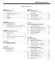
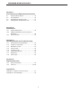

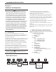
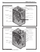


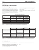
Table Of Contents
- Cover
- Table of Contents
- Table of Contents, Page 2
- Section 1 -GENERAL INFORMATION
- Section 2 -LOCATING THE APPLIANCE
- Section 3 -VENTING AND COMBUSTION AIR
- Section 4 -GAS SUPPLY AND PIPING
- Section 5 -PUMP REQUIREMENTS
- Section 6 -WATER CONNECTIONS -NTH BOILER
- Section 7 -ELECTRICAL AND WIRING DIAGRAMS
- Section 8 -THE USER INTERFACE
- 8.1 About the User Interface
- 8.2 Navigating the User Interface
- 8.3 The Home Display
- 8.4 Customizing your Home Display
- 8.5 Entering/Changing Control Settings
- 8.6 Quick Start
- Configuration and Setup
- 8.7 24 VAC Transformerwith Integral Circuit Breaker
- 8.8 Hydronic Heating Demand
- 8.9 Anti-Short-Cycle (ASC)
- 8.10 Outdoor Air Temperature Sensor
- 8.11 Outdoor Reset
- 8.12 Warm Weather Shutdown
- 8.13 Domestic Hot Water
- 8.14 About Lead Lag Operation
- 8.15 Adjusting CO2
- Section 9 -FIRST START-UP AND ADJUSTMENTINSTRUCTIONS
- Section 10 -MAINTENANCE
- Section 11 -OPERATING DETAILS AND TROUBLESHOOTING
- Section 12 -REPLACEMENT PARTS
- Appendix A -SOFTWARE CONTROL FUNCTIONS. Next 5 pages
- Appendix B -ERROR MESSAGES. Next 8 pages
- Back Cover. Contact information. Product and Service Videos

Page 4
LAARS Heating Systems
Table1. -PipingLocationDimensions,Sizes80-210
A B C D E F G J K M N
Size in cm in cm in cm in cm in cm in cm in cm in cm in cm in cm in cm
80 13½ 34 9½ 24 18¼ 46 7½ 19 10¾ 28 11¾ 30 13¾ 35 21 53 10¾ 27 15¼ 39 13 33
105 13½ 34 8 21 18¼ 46 6 16 10¾ 28 11¾ 30 14¼ 36 21 53 8¾ 22 15¼ 39 13 33
150 13¼ 34 5¼ 14 18¼ 46 3¼ 8 10¾ 28 7½ 19 14¼ 36 19½ 49 7½ 19 15¼ 39 13 33
210 20½ 52 5¼ 14 18¼ 46 3¼ 8 17¾ 45 7½ 19 14¼ 36 19½ 49 11¾ 30 15¼ 39 13 33
1.6 Dimensions
Table2. -OverallDimensions,Sizes80-210
W L H AIR INLET VENT
SIZE IN CM IN CM IN CM IN CM IN CM
80 25 64 19½ 49 38¼ 97 2 5.1 2 5.1
105 25 64 19½ 49 38¼ 97 2 5.1 2 5.1
150 25 64 19½ 49 38¼ 97 3 7.6 3 7.6
210 25 64 26¾ 68 38¼ 97 3 7.6 3 7.6
See Table 2
See Table 2