
Install Instructions
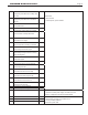


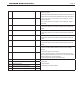
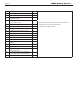
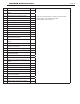
Table Of Contents
- Cover
- Table of Contents
- Table of Contents, Page 2
- Section 1 -GENERAL INFORMATION
- Section 2 -LOCATING THE APPLIANCE
- Section 3 -VENTING AND COMBUSTION AIR
- Section 4 -GAS SUPPLY AND PIPING
- Section 5 -PUMP REQUIREMENTS
- Section 6 -WATER CONNECTIONS -NTH BOILER
- Section 7 -ELECTRICAL AND WIRING DIAGRAMS
- Section 8 -THE USER INTERFACE
- 8.1 About the User Interface
- 8.2 Navigating the User Interface
- 8.3 The Home Display
- 8.4 Customizing your Home Display
- 8.5 Entering/Changing Control Settings
- 8.6 Quick Start
- Configuration and Setup
- 8.7 24 VAC Transformerwith Integral Circuit Breaker
- 8.8 Hydronic Heating Demand
- 8.9 Anti-Short-Cycle (ASC)
- 8.10 Outdoor Air Temperature Sensor
- 8.11 Outdoor Reset
- 8.12 Warm Weather Shutdown
- 8.13 Domestic Hot Water
- 8.14 About Lead Lag Operation
- 8.15 Adjusting CO2
- Section 9 -FIRST START-UP AND ADJUSTMENTINSTRUCTIONS
- Section 10 -MAINTENANCE
- Section 11 -OPERATING DETAILS AND TROUBLESHOOTING
- Section 12 -REPLACEMENT PARTS
- Appendix A -SOFTWARE CONTROL FUNCTIONS. Next 5 pages
- Appendix B -ERROR MESSAGES. Next 8 pages
- Back Cover. Contact information. Product and Service Videos

Page 68
LAARS Heating Systems
53 AC input phases reversed L 1. Check the module and display connections.
2. Check the module power supply and make sure that both
frequency and voltage meet the specications.
3. On 24 VAC applications, assure that J4 terminal 10 and J8
terminal 2 are connected together.
59 Internal Fault: Mux pin shorted L Internal Fault.
1. Reset module.
2. If fault repeats, replace module.
61 Anti short cycle H Will not be a lockout fault. Hold Only.
62 Fan speed not proved H Will not be a lockout fault. Hold Only.
63 SAFETY CHAIN (OFF)
To diagnose, test all of the following safety
devices if they are installed:
Condensate Level Switch – All Models
Heat Exchanger Fusible Link – All Models
Optional Flow Switch
Additional High Limit (Field Supplied)
Optional Pressure Switch
Optional Low Water Cut Off
Low Pressure gas switch – Inlet Side of
Gas Valve (Standard Equipment on CSD-
1 Models)
High Pressure gas switch – Outlet Side of
Gas Valve (Standard Equipment on CSD-
1 Models)
H
1. Reset the low gas pressure valve and the high gas pressure
valve.
2. Check for power at Terminal Block 8 (TB8 for the ‘Safety
Chain’ components. See Figure 16 on page 25
3. Check wiring and correct any faults.
4. Check all safety interlocks connected to the safety circuit to
assure proper function.
5. If code persists, contact Tech Support.
64 PII (Pre-Ignition Interlock) OFF H or L 1. Check wiring and correct any faults.
2. Check Preignition Interlock switches to assure proper
functioning.
3. Check the valve operation.
4. Reset and sequence the module; monitor the PII status.
5. If code persists, replace the module.
67 ILK (Interlock) OFF H or L 1. Check wiring and correct any possible shorts.
2. Check Interlock (ILK) switches to assure proper function.
3. Verify voltage through the interlock string to the interlock input
with a voltmeter.
4. If steps 1-3 are correct and the fault persists, replace the
module.
68 ILK (Interlock) ON H or L
70 Wait for leakage test completion H 1. Internal Fault. Reset module.
2. If fault repeats, replace module.
78 Demand Lost in Run H 1. Check wiring and correct any possible errors.
2. If previous steps are correct and fault persists, replace the
module.
79 Outlet high limit H or L 1. Check wiring and correct any possible errors.
2. Replace the outlet high limit.
3. If previous steps are correct and fault persists, replace the
module.