
Install Instructions
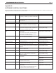
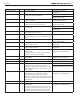
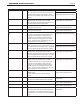
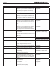
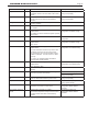

Table Of Contents
- Cover
- Table of Contents
- Table of Contents, Page 2
- Section 1 -GENERAL INFORMATION
- Section 2 -LOCATING THE APPLIANCE
- Section 3 -VENTING AND COMBUSTION AIR
- Section 4 -GAS SUPPLY AND PIPING
- Section 5 -PUMP REQUIREMENTS
- Section 6 -WATER CONNECTIONS -NTH BOILER
- Section 7 -ELECTRICAL AND WIRING DIAGRAMS
- Section 8 -THE USER INTERFACE
- 8.1 About the User Interface
- 8.2 Navigating the User Interface
- 8.3 The Home Display
- 8.4 Customizing your Home Display
- 8.5 Entering/Changing Control Settings
- 8.6 Quick Start
- Configuration and Setup
- 8.7 24 VAC Transformerwith Integral Circuit Breaker
- 8.8 Hydronic Heating Demand
- 8.9 Anti-Short-Cycle (ASC)
- 8.10 Outdoor Air Temperature Sensor
- 8.11 Outdoor Reset
- 8.12 Warm Weather Shutdown
- 8.13 Domestic Hot Water
- 8.14 About Lead Lag Operation
- 8.15 Adjusting CO2
- Section 9 -FIRST START-UP AND ADJUSTMENTINSTRUCTIONS
- Section 10 -MAINTENANCE
- Section 11 -OPERATING DETAILS AND TROUBLESHOOTING
- Section 12 -REPLACEMENT PARTS
- Appendix A -SOFTWARE CONTROL FUNCTIONS. Next 5 pages
- Appendix B -ERROR MESSAGES. Next 8 pages
- Back Cover. Contact information. Product and Service Videos

Page 66
LAARS Heating Systems
Appendix B -
ERROR MESSAGES
This table includes a listing of the faults that might be generated by the controller, and displayed on the Operator
Interface. Some of these can be corrected by an installer changing a parameter, while other conditions are more
complicated, and will require a service technician.
The rst column lists the code number that will appear at the beginning of the Lockout or Hold message. The
second column lists a short description of the condition. The third column shows whether the condition will
cause a Hold, or Lockout, or both. The fourth column lists some suggestions for corrective action.
Code Description L or H Procedure
1 Uncongured safety data L 1. New device, complete device conguration and safety
verication.
2. If fault repeats, replace module.
2. Waiting for safety
data verication
L 1. Device in Conguration mode and safety parameters need
verication and a device needs reset to complete verication.
2. Conguration ended without verication, re enter
conguration, verify safety.
parameters and reset device to complete verication.
3. If fault repeats, replace module.
3 Internal fault:
Hardware fault
H
Internal fault
1. Reset module
2. If fault repeats, replace module.
4 Internal fault:
Safety Relay key feedback error
H
5 Internal fault:
Unstable power (DC) output
H
6 Internal fault:
Invalid processor clock
H
7 Internal fault:
Safety relay drive error
H
8 Internal fault:
Zero crossing not detected
H
9 Internal fault:
Flame bias out of range
H
10 Internal fault:
Invalid burner control state
L
11 Internal fault:
Invalid burner control state ag
L
12 Internal fault:
Safety relay drive cap short
H
13 Internal fault:
PII (Pre-Ignition Interlock) shorted to ILK
(Interlock)
H or L
15 Internal fault:
Safety relay test failed due to feedback
ON
L
16 Internal fault:
Safety relay test failed due to safety relay
OFF
L
Table23. PlaceholderforAppendixB