
Install Instructions

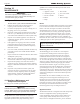
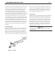

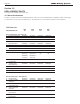
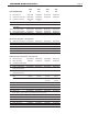

Table Of Contents
- Cover
- Table of Contents
- Table of Contents, Page 2
- Section 1 -GENERAL INFORMATION
- Section 2 -LOCATING THE APPLIANCE
- Section 3 -VENTING AND COMBUSTION AIR
- Section 4 -GAS SUPPLY AND PIPING
- Section 5 -PUMP REQUIREMENTS
- Section 6 -WATER CONNECTIONS -NTH BOILER
- Section 7 -ELECTRICAL AND WIRING DIAGRAMS
- Section 8 -THE USER INTERFACE
- 8.1 About the User Interface
- 8.2 Navigating the User Interface
- 8.3 The Home Display
- 8.4 Customizing your Home Display
- 8.5 Entering/Changing Control Settings
- 8.6 Quick Start
- Configuration and Setup
- 8.7 24 VAC Transformerwith Integral Circuit Breaker
- 8.8 Hydronic Heating Demand
- 8.9 Anti-Short-Cycle (ASC)
- 8.10 Outdoor Air Temperature Sensor
- 8.11 Outdoor Reset
- 8.12 Warm Weather Shutdown
- 8.13 Domestic Hot Water
- 8.14 About Lead Lag Operation
- 8.15 Adjusting CO2
- Section 9 -FIRST START-UP AND ADJUSTMENTINSTRUCTIONS
- Section 10 -MAINTENANCE
- Section 11 -OPERATING DETAILS AND TROUBLESHOOTING
- Section 12 -REPLACEMENT PARTS
- Appendix A -SOFTWARE CONTROL FUNCTIONS. Next 5 pages
- Appendix B -ERROR MESSAGES. Next 8 pages
- Back Cover. Contact information. Product and Service Videos

Page 55
NEOTHERM Residential Boilers
SIZE SIZE SIZE SIZE
ITEM DESCRIPTION 80 105 150 210
25 Mounting Rail R15D1004 R15D1004 R15D1004 R30D1004
27 Condensate Trap Assy R20D4020 R20D4020 R20D4020 R20D4020
28 Heat Exch. Rail Clip R50D1006 R50D1006 — —
(2) (2)
30 PVC Reducer — — RP2053000 RP2053000
30a CPVC Reducer RD2010501 RD2010501 RP2065600 RP2065600
or Coupling
30b 2” Dia. Pipe, CPVC RD2010212 RD2010212 RD2010213 RD2010213
31 Hose Barbed Adapter RP2067100 RP2067100 RP2056100 RP2056100
33 Air Inlet/Exhaust Bracket R8D3005 10D3005 R20D3120 R20D3120
GasTrainComponents–See Figure 41
40 Combustion Air Blower RA2113700 RA2113700 RA2107500 RA2114200
41 Gas Valve/Venturi RV2017900 RV2017901 RV2017902 RV2017903
47 Gas Valve O-Ring R30-227 R30-227 R30-227 R30-227
51 Duct/Venturi Transition R10D5021 R10D5021 R10D5021 R10D5013
52 Gas Supply Pipe RP2051700 RP2051400 RP2051400 RP2051400
55 Air Inlet Flex Hose D0091403 RD0091403 RD0091403 D0091401
HeatExchangerComponents–See Figure 43
60 Heat Exchanger RS2106900 RS2105500 RS2105800 RS2105700
61 Pump Assembly R8D4110 R10D4110 R10D4110 R20D4140
62 Low Water Cutoff Switch — — — —
63 Inlet Water Temp Sensor RE2320600 RE2320600 RE2320600 RE2320600
64 Duplex Outlet Water RE2319900 RE2319900 RE2319900 RE2319900
Temperature Sensor
65 Duplex Stack RE2319700 RE2319700 RE2319700 RE2319700
Temperature Sensor
66 Pressure Relief Valve, R51-182 R51-182 R51-182 R51-182
NTH
(30 PSI) (30 PSI) (30 PSI) (30 PSI)
Pressure Relief Valve, A2114802 A2114802
(125 PSI) (125 PSI)
67 Air Vent R1-592 R1-592 R1-592 R1-592
68 Burner Door w/gasket RS2112801 RS2112801 RS2112801 RS2112801
68A Burner Door Gasket
(rubber)
R2069400 R2069400 R2069400 R2069400
69 Burner Gasket RS2108500 RS2108500 RS2108500 RS2108500
69A Gasket Set RS2109100 RS2109100 RS2109100 RS2109100
(burner gasket, ignitor gasket, sensor gasket & burner door gasket)
70 Front Refractory Tile RT2109001 RT2109001 RT2109001 RT2109001
71 Rear Refractory Tile R50D2021 R50D2021 R50D2021 R50D2021
72 Main Burner w/gasket R2069101 R2069102 R2069103 R2069104
73 Flame Sensor w/gasket R2069200 R2069200 R2069200 R2069200
74 Ignitor w/gasket R2069300 R2069300 R2069300 R2069300
74A Ignitor Gasket RW2013300 RW2013300 RW2013300 RW2013300