
Install Instructions

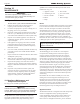
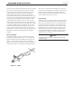

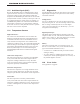

Table Of Contents
- Cover
- Table of Contents
- Table of Contents, Page 2
- Section 1 -GENERAL INFORMATION
- Section 2 -LOCATING THE APPLIANCE
- Section 3 -VENTING AND COMBUSTION AIR
- Section 4 -GAS SUPPLY AND PIPING
- Section 5 -PUMP REQUIREMENTS
- Section 6 -WATER CONNECTIONS -NTH BOILER
- Section 7 -ELECTRICAL AND WIRING DIAGRAMS
- Section 8 -THE USER INTERFACE
- 8.1 About the User Interface
- 8.2 Navigating the User Interface
- 8.3 The Home Display
- 8.4 Customizing your Home Display
- 8.5 Entering/Changing Control Settings
- 8.6 Quick Start
- Configuration and Setup
- 8.7 24 VAC Transformerwith Integral Circuit Breaker
- 8.8 Hydronic Heating Demand
- 8.9 Anti-Short-Cycle (ASC)
- 8.10 Outdoor Air Temperature Sensor
- 8.11 Outdoor Reset
- 8.12 Warm Weather Shutdown
- 8.13 Domestic Hot Water
- 8.14 About Lead Lag Operation
- 8.15 Adjusting CO2
- Section 9 -FIRST START-UP AND ADJUSTMENTINSTRUCTIONS
- Section 10 -MAINTENANCE
- Section 11 -OPERATING DETAILS AND TROUBLESHOOTING
- Section 12 -REPLACEMENT PARTS
- Appendix A -SOFTWARE CONTROL FUNCTIONS. Next 5 pages
- Appendix B -ERROR MESSAGES. Next 8 pages
- Back Cover. Contact information. Product and Service Videos

Page 49
NEOTHERM Residential Boilers
factory for proper trouble shooting practices prior to replacing
the control. If control replacement is required, turn off all
power to the appliance and shut off all manual gas valves
to the appliance. Remove the front door to the appliance
and the plastic bezel and the control panel. Remove all
wire connections from the control board. The control board
connections are keyed to only allow connection in the proper
location, but proper handling techniques should be used to
avoid damage to the wiring or connectors. To remove the
control, push in on the two tabs on the left side of the board
to unlatch the clips from the control panel. Rotate the control
around the fastening points on the right side of the control
to remove the hooks from the control panel. To replace the
control, repeat the steps listed above in the reverse orders
making sure to connect all wires in the proper locations. Place
the appliance in operation following the steps outlined in
Section 9.
IgnitorAssembly
The ignitor assembly is a two rod system that consists of a
ground rod and a spark rod (See Figure 37). To remove the
ignitor assembly, shut off the 120 Volt power supply to the
appliance. Turn off all manual gas valves connecting the
appliance to the main gas supply line. Remove the front door
of the boiler to gain access to the ignitor assembly. Remove
the two wires connected to the assembly. Then remove the
two bolts connecting the ignitor assembly to the burner door.
If the old ignitor assembly is determined to be defective,
install a new ignitor assembly (check that the spark gap is
3/16”). Replace the gasket if necessary.
FlameSensor
The ame sensor is a single rod system. To replace the ame
sensor electrode, shut off the 120 Volt power supply to the
boiler. Turn off all manual gas valves connecting the boiler
to the main gas supply line. Remove the front door of the
boiler to gain access to the ame sensor electrode. Remove
the ame sensor wire from the electrode. Remove the two
bolts fastening the electrode to the burner doors. Remove
and replace the old ame sensor gasket. If the old electrode
is determined to be defective, install a new ame sensor
electrode in the reverse order.
Caution
The ignitor and sensor may be hot, and can cause
burns or injury.
Figure 37. - Ignitor
NOTES:
SPARK IGNITOR1.
GIANNONI #gm10-35-108-01
1.08
.18
W20131
3.1
3/16”